
Control for product dispenser energy storage device

a technology of energy storage device and product dispenser, which is applied in the direction of liquid transfer device, liquid handling, instruments, etc., can solve the problems of reducing affecting the efficiency of energy storage device, etc., to achieve the effect of increasing the energy ra

Active Publication Date: 2015-11-12
GOJO IND INC
View PDF4 Cites 17 Cited by
  • Summary
  • Abstract
  • Description
  • Claims
  • Application Information

AI Technical Summary

Benefits of technology

The patent describes a dispensing system for a product that includes a housing, a refill reservoir, a pump, and a motor. The system has a battery integrated into the refill reservoir and a controller that draws power from the battery to activate the motor. The motor drives the pump to dispense the product. The rate at which the controller draws power from the battery changes based on factors like the rate at which the user activates the motor and the amount of fluid remaining in the reservoir. The controller can also selectively initiate discharging energy from the battery or an energy source mounted to the dispenser housing to recharge the intermediate energy storage device. The system also includes a sensor to detect user motion and automatically activate the motor to dispense the product. The controller can also monitor the level of energy stored in the intermediate energy storage device and adjust the discharge rate accordingly.

Problems solved by technology

However, one problem with dispensers of this type relates to the maintenance and replacement of the batteries.
It is difficult or impossible to tell how much power is remaining in the batteries of a dispenser, or how spurts in usage will drain the remaining power in the batteries.
However, coin cells are incapable of rapidly discharging energy.
If power is drawn too quickly from a coin cell, the useful life of the battery can be greatly reduced.
However, capacitors have limited storage capacity and drain quickly with repeated use.
In busy environments, the capacitor may be incapable in keeping up with dispensing activity.
In environments with less traffic, energy stored in the capacitors may dissipate over time.
Even though the capacitor may be recharged from the onboard batteries, energy is being used but fluid product is not being dispensed.
In this instance, the batteries may be depleted long before the reservoir is empty of product.

Method used


Image

  • Control for product dispenser energy storage device
  • Control for product dispenser energy storage device
  • Control for product dispenser energy storage device

Examples


Embodiment Construction

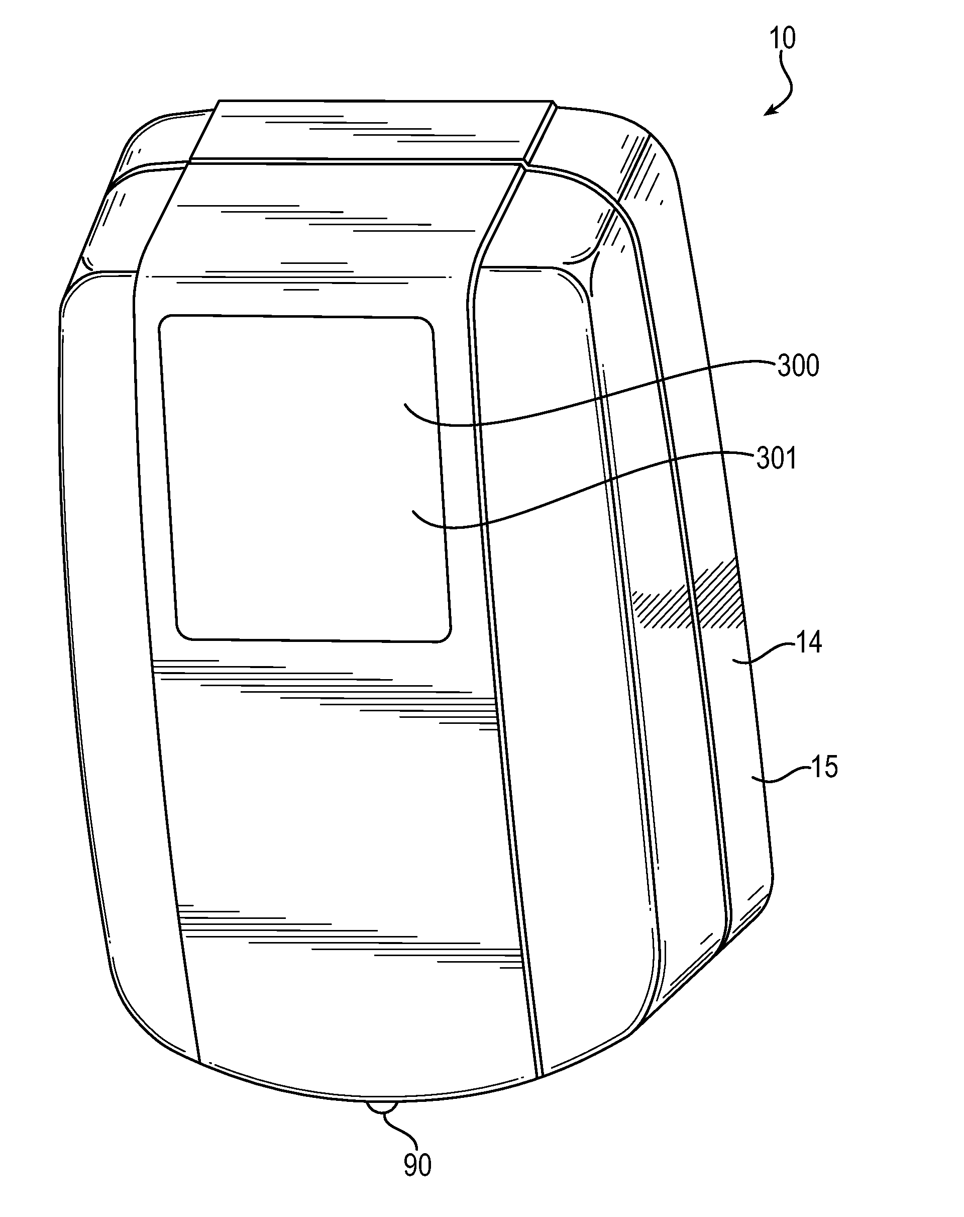
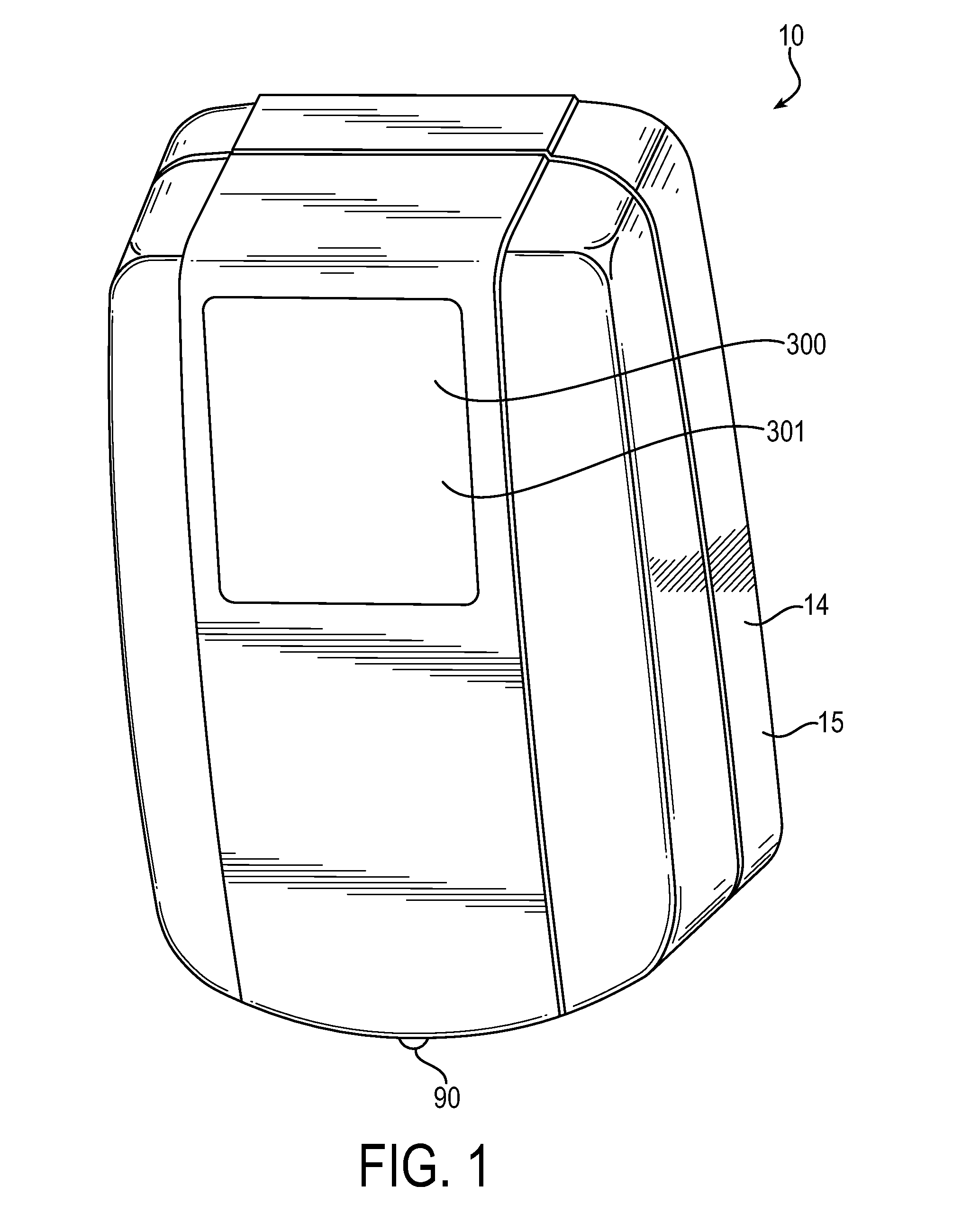
[0041]A product dispensing system, depicted in FIG. 1, dispenses a measured amount of fluid product according to the embodiments of the subject invention. In one exemplary instance, the dispensing system, shown generally at 10, dispenses hand care products like soap, lotion or hand sanitizer, although other types of products may be similarly dispensed from the dispensing system.

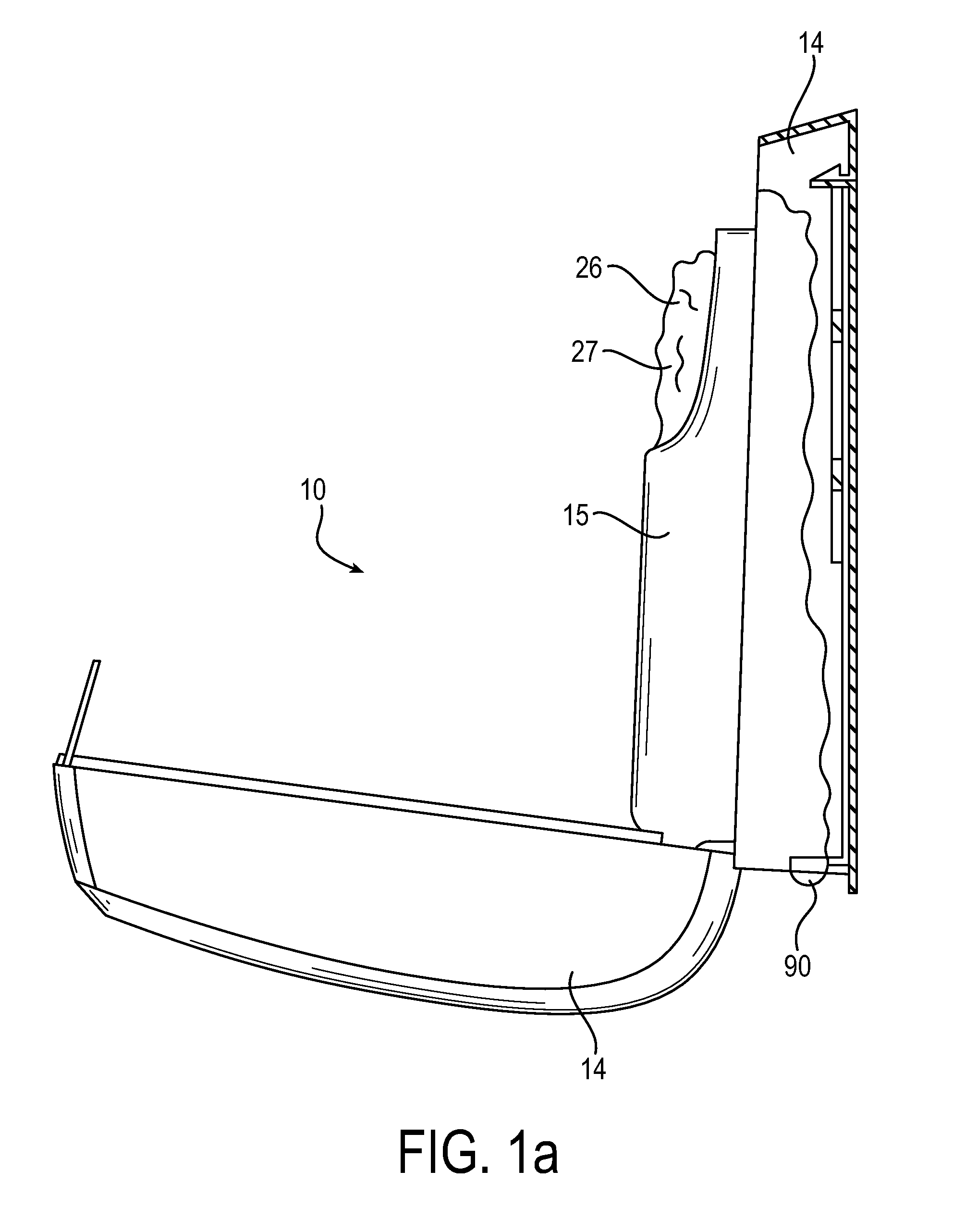
[0042]In the embodiment depicted in FIGS. 1 and 1a, the dispensing system 10, also referred to as fluid dispenser 10, includes a dispenser housing 14 or base. The dispenser housing 14 is made of one or more walls 15 constructed to support the components of the fluid dispenser 10. Plastic may be used for cost effective manufacturing of the dispenser housing 14, as well as other components of the system. A fluid reservoir 26 supplies fluid product to the fluid dispenser 10 and is mounted to the dispenser housing 14 in an inverted manner. The walls 15 of the dispenser housing 14 may form a concave, open top sect...


PUM


Abstract

An energy storage device, like for example a supercapacitor, is used to provide power to activate a motor for dispensing a dosed amount of hand care product. The energy storage device or supercapacitor is recharged from an energy supply source, e.g. batteries, integrated into the replaceable refill reservoir and / or mounted into the dispenser housing. A controller directs energy discharged from the energy supply source(s) at one of a plurality of discharge energy rates for recharging the energy storage device. Depending on the number of dispense events that occur with a given time interval, the controller may vary the rate at which the energy is discharged from the energy supply source(s) to recharge the energy storage device.

Description

RELATED APPLICATIONS[0001]This patent application claims priority to patent application Ser. No. 61 / 977,962, titled DISCHARGE RATE CONTROL FOR PRODUCT DISPENSER ENERGY STORAGE DEVICE, filed on Apr. 10, 2014, which is incorporated herein by reference in its entirety.FIELD OF THE INVENTION[0002]The current invention relates generally to fluid product dispensers and in particular to refill reservoirs used in touch-free dispensers. More specifically, the current invention relates to refill reservoirs that include a source of energy that powers the fluid dispenser and methods of discharging that energy.BACKGROUND OF THE INVENTION[0003]It is commonplace for publicly accessible facilities to provide soap dispensers in washrooms and other areas. Some systems are designed to receive disposable refill units produced in a sanitary environment. When empty of product, the whole reservoir is replaced along with the accompanying nozzle and pump. In this way, every part wetted by soap is disposed o...

Claims


Application Information

Patent Timeline
IPC IPC(8): A47K5/12H02J7/00
CPCA47K5/1217H02J7/0052A47K5/1211A47K5/1207H02J7/0063H02J7/345H02J7/007188H02J7/007182Y02E60/10H02J7/00
Inventor BULLOCK, MARK A.LIGHTNER, BRADLEY L.ZOSIMADIS, PANAGIOTI
Owner GOJO IND INC
Learn More