Rotation device and rotor compressor and fluid motor having the same

a technology of rotor compressor and fluid motor, which is applied in the direction of liquid fuel engines, bearing unit rigid supports, machines/engines, etc., can solve the problems of limiting the application of rotor compressor to large-scale air compressors and air compressors used, affecting the service life of the entire rotor compressor, and affecting the service life of the rotor compressor. , to achieve the effect of good reliable sealing of the rotor, low vibration and noise, and cost reduction

Active Publication Date: 2015-11-12
BEIJING ROSTAR TECH
View PDF29 Cites 16 Cited by
  • Summary
  • Abstract
  • Description
  • Claims
  • Application Information

AI Technical Summary

Benefits of technology

[0013]It can be seen from the above technical solutions that the rotation device and the rotor compressor and the fluid motor having the same according to the present invention have the following advantageous technical effects.
[0014](1) The rolling bearing is used between the eccentric shaft and the rolling piston wheel. With the rolling bearing, an oil-free or minimal-oil (i.e., small-range local oil lubrication) rotor compressor is achieved, thereby overcoming the defects resulted from using of a great deal of lubricating oil. As a result, the rotation device can be applied to fields of large compressors and air compressors.
[0015](2) A radial clearance is employed between an outer cylindrical surface of the outer ring of the rolling bearing and a rolling bearing mounting and positioning inner cylindrical surface, and an elastic preloading element is clamped between them. With the elastic preloading element, not only excessively rigorous accuracy requirements for radial fit dimensions of parts constituting the eccentric rotor can be avoid and the cost is reduced, but also a function of absorbing vibration and noise is achieved, while good reliable sealing of the rotor of the compressor is achieved.
[0016](3) A weight counterbalancing solution is adopted to alleviate problem of momentum unbalance of the rotation device caused by eccentric rotation. The rotor compressor subjected to rotor momentum balanced design further conforms to principles of precision machine technology. In operation, the rotor compressor is low in vibration and noise.
[0017](4) A resetting urging force of a compression spring is directly transmitted to a side position of a rotary valve body close to a rotary valve body head through a resetting pin. Therefore, a contact pressure of the rotary valve body head pressed against an outer cylindrical surface of a planetary piston roller can be accurately adjusted, achieving reliable sealing with a minimum sliding frictional force and improving an operational reliability of the rotation device.
[0018](5) The rotary valve body resetting pin is made in a structure of a conventional pressure cylinder, or a stronger, stabler, more accurate and longer-life time pneumatic element is used to control swing of the rotary valve body, thereby ensuring operational reliability and convenience of maintenance of the entire rotation device.
[0019](6) A roller or a swing seal slider is provided at a distal end of the rotary valve body. Thereby, a frictional force between the rotary valve body and the rolling piston wheel is further decreased and a working efficiency is improved.

Problems solved by technology

However, when the rotor compressor shown in FIG. 1 operates in a high-intensity working condition, and especially when a frequency of rotation is very high, energy loss caused by sliding frictions between sliding surfaces of the driving shaft 4 with the eccentric shaft portion and of the rolling rotor 2 and the eccentric sleeve 3 are relatively large and thus these sliding surfaces need to be lubricated with oil.
Since an electric motor for driving rotation of the rotor compressor is mounted within the housing, a high-temperature high-pressure environment formed within the housing goes badly against insulation and heat dissipation of the drive electric motor and thus the electric motor will be easily overheated.
This limits application of the rotor compressor to large-scale air compressors and air compressors used at a low temperature.
Since the helical spring operates in a high-intensity working condition for a long time, it will very easily fault to be broken, thereby affecting a service life of the entire rotor compressor.
Furthermore, due to presence of a lever effect, a force between the swing stop and the rolling rotor 2 cannot be easily controlled.
If the force is too large, not only wear of the swing stop is increased, but a power of the compressor is also consumed; while if the force is too small, sealing of the cylinder cannot be ensured.
If there is no corresponding measure, the contact portions will be very easily damaged.
Although wear and seal problems of the contact portions can be solved in this way, it is impossible to achieve rolling between the outer cylindrical surface of the rolling seal sleeve 2 and a cylindrical inner wall of the cylinder block 1, thereby resulting in frictional wear and occurrence of clearance issues.
Although the clearance in the portion where the cylinder block and the seal sleeve come into contact with each other can be filled with oil, this will bring about a problem of separating the compression medium from the lubricating oil.

Method used


Image

  • Rotation device and rotor compressor and fluid motor having the same
  • Rotation device and rotor compressor and fluid motor having the same
  • Rotation device and rotor compressor and fluid motor having the same

Examples


Embodiment Construction

[0039]The objects, technical solutions and advantages of the present invention will be apparent and more readily appreciated from the following description of embodiments taken in conjunction with the accompanying drawings. It is noted that the same or similar elements are indicated by the same reference symbols in the description and the drawings. Implementing forms that are not described and shown in the drawings are those known by those skilled in the art.

[0040]In order to facilitate understanding, main elements involved in embodiments of the present invention are first numbered as follow.

LIST OF SYMBOLS OF MAIN ELEMENTS OF THE PRESENT INVENTION

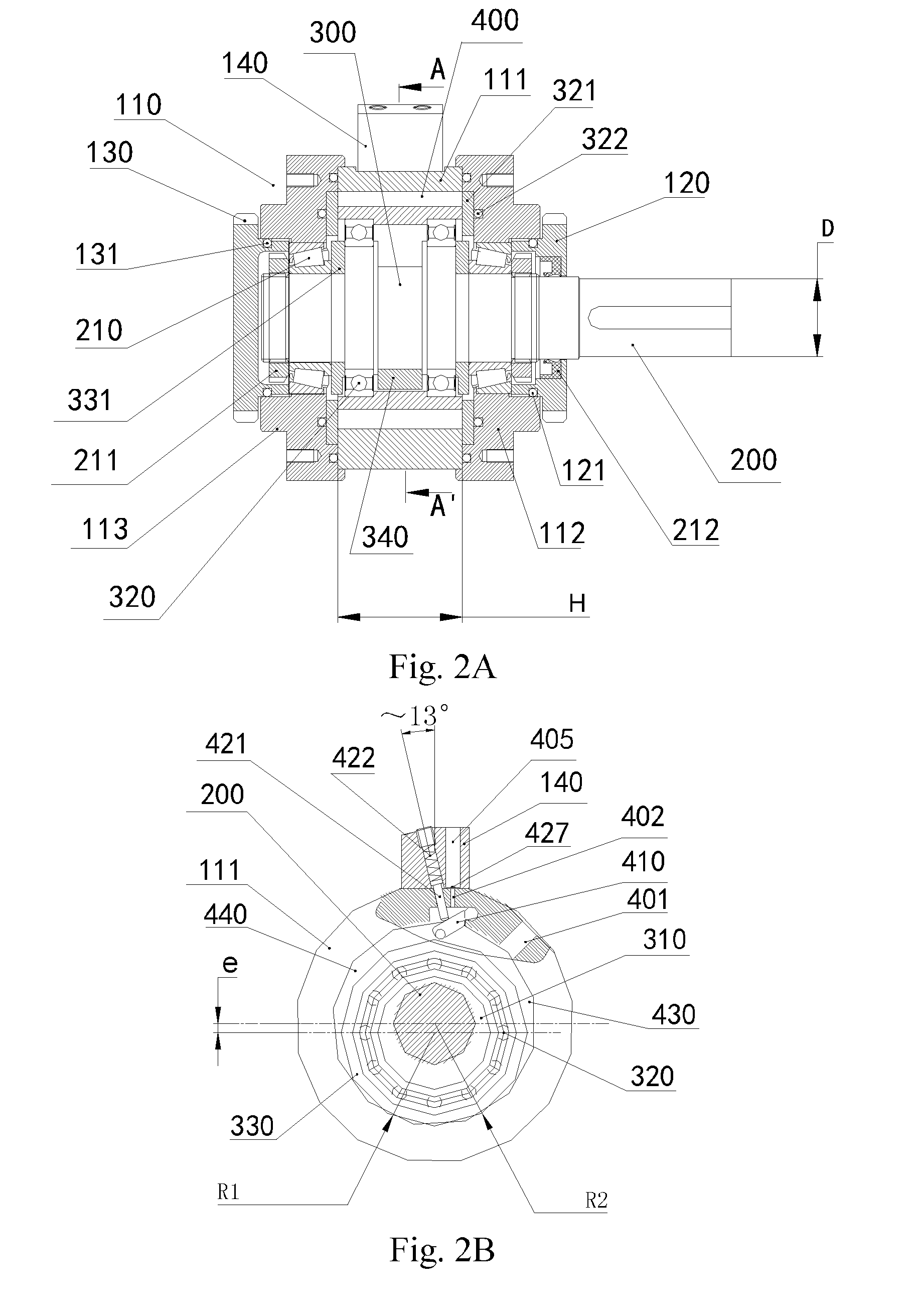
[0041]110—cylinder block;[0042]111—cylinder block body;[0043]112—front cylinder cover;[0044]113—rear cylinder cover;[0045]120—front end cover;[0046]121—front end cover seal rubber ring;[0047]130—rear end cover;[0048]131—rear end cover seal rubber ring;[0049]140—cylinder head;[0050]200—main shaft;[0051]210—main shaft bearing;[0052]211—beari...


PUM


Abstract

A rotating device includes a cylinder body, a front end cover, a rear end cover, a main shaft, an eccentric rotor assembly and an isolation mechanism. The eccentric rotor assembly includes an eccentric shaft, a rolling piston wheel and at least one rolling bearing. In the rotating device, the eccentric shaft is isolated from the rolling piston wheel by the rolling bearing and the two are rotated, and the cylinder body is reliably sealed by an elastic pre-tightening force. Further provided are a rotor compressor using the rotating device, and a fluid motor. A rotating valve body and a rotating valve body reset mechanism in the rotating device are also improved.

Description

BACKGROUND OF THE INVENTION[0001]1. Field of the Invention[0002]The present invention relates to the field of fluid machinery, and in particular to a rotation device, and a rotor compressor and a fluid motor having the same.[0003]2. Description of the Related Art[0004]At present, commercially available displacement compressors used most widely are mainly divided into four types: reciprocating piston compressors, screw compressors, scroll compressors and rotor compressors. For a rotor compressor, when a main shaft is rotating, an eccentric rotor revolves in close contact with an inner wall of a cylinder so as to change a crescent volume space periodically, thereby accomplishing a suction process, a compression process, and an exhaust process. Since the compression process of the rotor compressor is smooth and balanced, the rotor compressors have been applied widely to household refrigeration apparatuses such as air conditioners and refrigerators.[0005]FIG. 1 is a schematic structural...

Claims


Application Information

Patent Timeline
Patent Type & Authority Applications(United States)
IPC IPC(8): F01C1/38F04C18/38F01C21/08
CPCF01C1/38F04C18/38F01C21/0827F01C1/46F01C19/02F01C21/02F01C21/0845F04C2240/52F04C2240/56F04C18/46F16C35/077F16C23/08F04C2240/807F16C27/04F16C25/08F16C27/066F04C2/46F04C2240/50F04C2/38F01C11/004F01C21/0863F01C21/0872F01C21/0854F04C11/003F04C23/003
Inventor YAO, FRANKYAO, QIHUAI
Owner BEIJING ROSTAR TECH
Why Eureka
Try Eureka