
Hydrodynamic bearing device, spindle motor having the same, and recording disk driving device

a technology of hydrodynamic bearings and driveshafts, which is applied in the direction of sliding contact bearings, instruments, record information storage, etc., can solve the problems of reducing the lifespan of the motor, lubricating fluid may easily leak to the exterior of the hydrodynamic bearing device, etc., and achieve the effect of reducing the leakage speed of lubricating fluid

Inactive Publication Date: 2015-11-12
SAMSUNG ELECTRO MECHANICS CO LTD
View PDF5 Cites 4 Cited by
  • Summary
  • Abstract
  • Description
  • Claims
  • Application Information

AI Technical Summary

Benefits of technology

The invention prevents lubricating fluid leakage during operation by creating a region in the storage space where force is increased, reducing the speed of lubricating fluid leakage, and preventing scattering of lubricating fluid due to a pressure differential of 2 KPa. This results in improved performance and reliability of the invention.

Problems solved by technology

As a result of such a pressure differential, the lubricating fluid may easily leak to the exterior of the hydrodynamic bearing device to then dissipate.
However, a lifespan of a motor decreases due to evaporation of the small amount of injected lubricating fluid.

Method used


Image

  • Hydrodynamic bearing device, spindle motor having the same, and recording disk driving device
  • Hydrodynamic bearing device, spindle motor having the same, and recording disk driving device
  • Hydrodynamic bearing device, spindle motor having the same, and recording disk driving device

Examples


Embodiment Construction

[0048]The following detailed description is provided to assist the reader in gaining a comprehensive understanding of the methods, apparatuses, and / or systems described herein. However, various changes, modifications, and equivalents of the methods, apparatuses, and / or methods described herein will be apparent to one of ordinary skill in the art. For example, the sequences of operations described herein are merely examples, and are not limited to those set forth herein, but may be changed as will be apparent to one of ordinary skill in the art, with the exception of operations necessarily occurring in a certain order. Also, descriptions of functions and constructions that are well known to one of ordinary skill in the art may be omitted for increased clarity and conciseness.

[0049]Throughout the drawings and the detailed description, the same reference numerals refer to the same elements. The drawings may not be to scale, and the relative size, proportions, and depiction of elements ...


PUM

PropertyMeasurementUnit
forceaaaaaaaaaa
volumeaaaaaaaaaa
sizeaaaaaaaaaa

Abstract

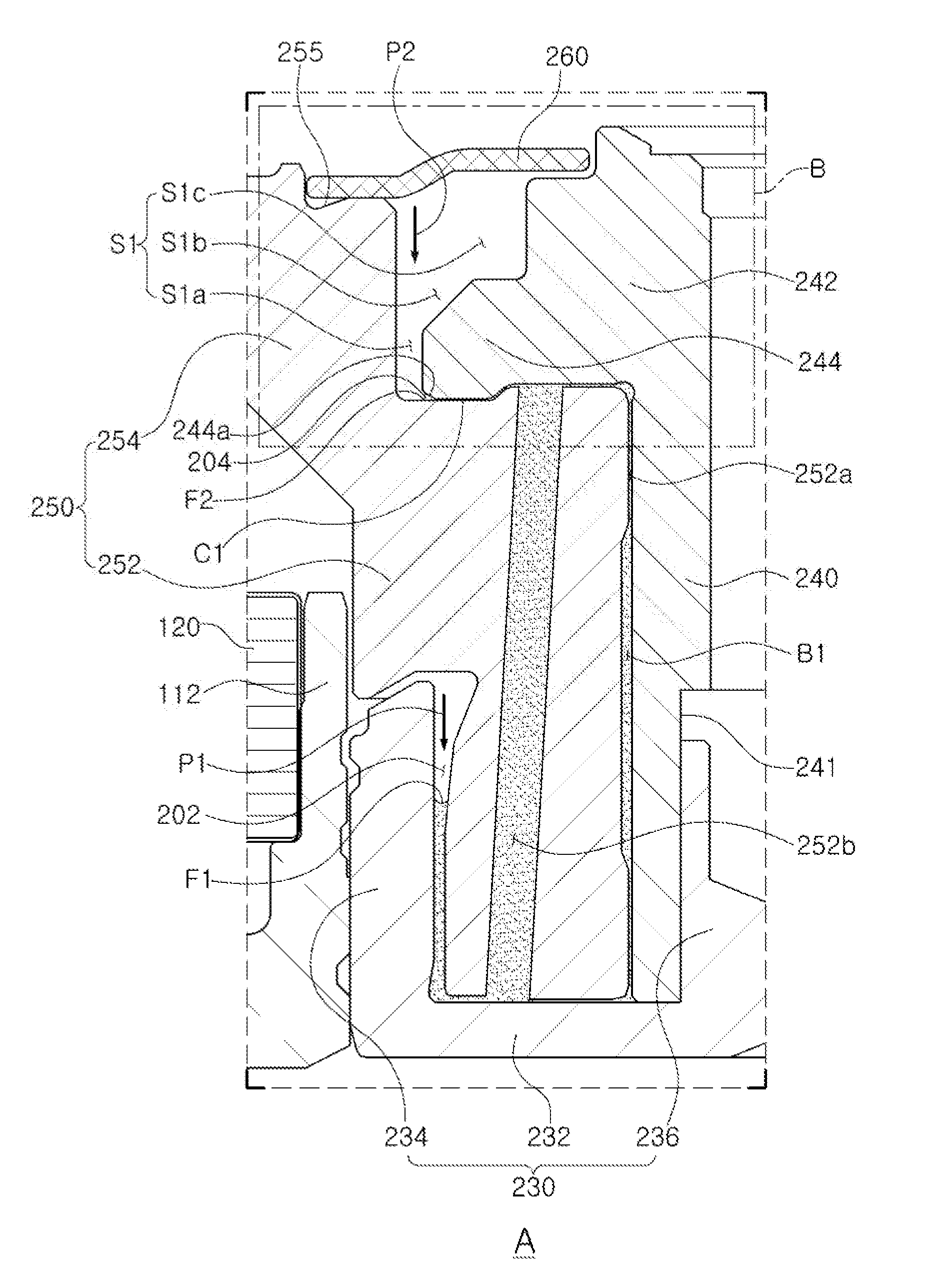
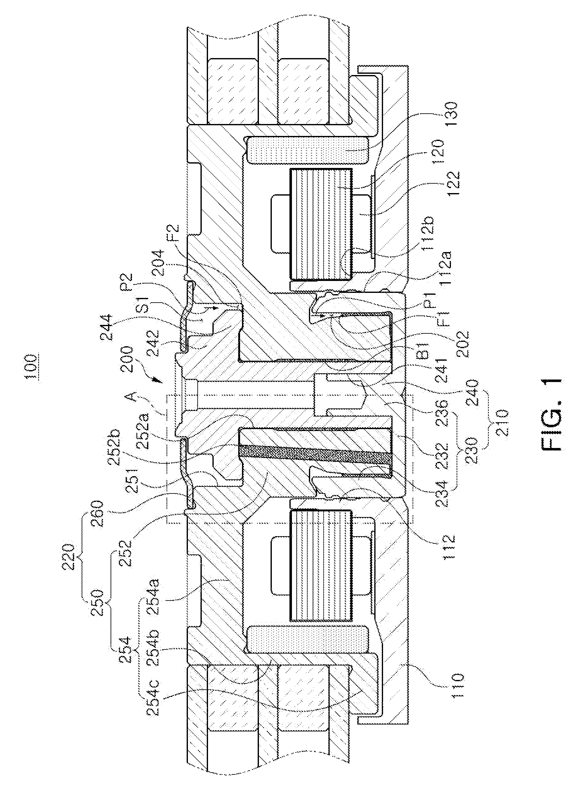
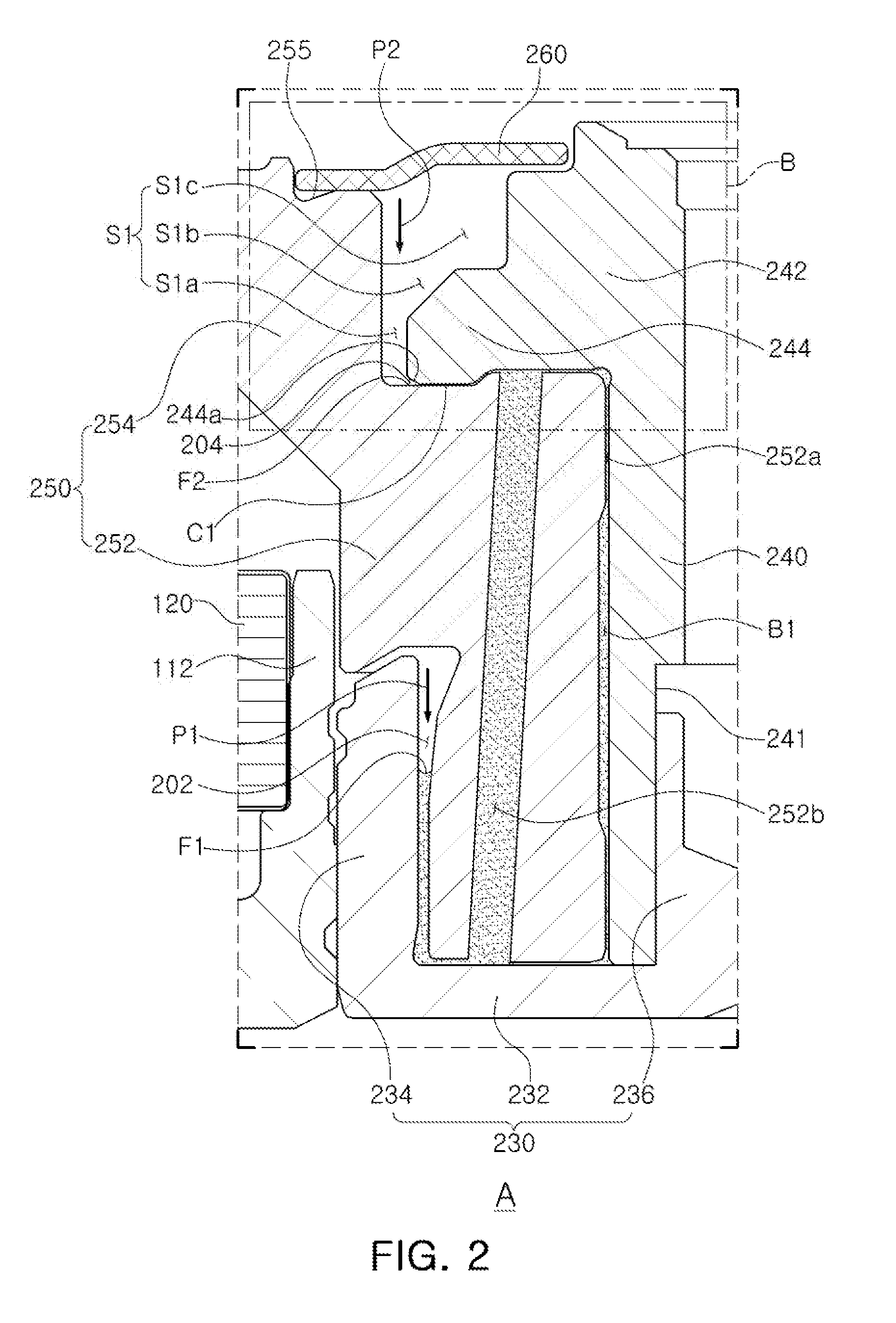
A hydrodynamic bearing device includes a stator and a rotor. The rotor forms a bearing clearance and a sealing part connected with the bearing clearance. A liquid-vapor interface is disposed in the sealing part together with the stator, and the bearing clearance is filled with a lubricating fluid. The stator and the rotor form a storage space connected with the sealing part to receive the lubricating fluid. The storage space has a region in which force applied to the liquid-vapor interface increases by a capillary phenomenon at a time that the lubricating fluid leaks to fill the bearing clearance.

Description

CROSS-REFERENCE TO RELATED APPLICATIONS[0001]This application claims the priority and benefit under 35 USC 119(a) of Korean Patent Application No. 10-2014-0054585 filed on May 8, 2014, and Korean Patent Application No. 10-2014-0120213 filed on Sep. 11, 2014, with the Korean Intellectual Property Office, the disclosures of which are incorporated herein by reference.BACKGROUND[0002]1. Field[0003]The present disclosure relates to a hydrodynamic bearing device, a spindle motor having the same, and a recording disk driving device.[0004]2. Description of Related Art[0005]In general, a so-called fixed-shaft type spindle motor, in which a shaft having excellent vibration characteristics is fixed to a base member, is mounted on an information recording and reproducing device, such as a recording disk driving device for a server.[0006]Meanwhile, in the case in which a fixed shaft is provided in a driving motor, a plurality of liquid-vapor interfaces are formed in a hydrodynamic bearing device...

Claims


Application Information

Patent Timeline
Patent Type & Authority Applications(United States)
IPC IPC(8): F16C17/10G11B19/28G11B19/247H02K7/08
CPCF16C17/107G11B19/247G11B19/28H02K7/085G11B19/2036F16C2370/12F16C33/745F16C33/1085
Inventor JANG, HO KYUNGJUNG, KYUNG MOONKIM, YONG SIKKIM, JAE HYUK
Owner SAMSUNG ELECTRO MECHANICS CO LTD
Learn More