Reduced Friction Piston Rings

Inactive Publication Date: 2015-11-12
MEACHAM G B KIRBY
View PDF16 Cites 3 Cited by
  • Summary
  • Abstract
  • Description
  • Claims
  • Application Information

AI Technical Summary

Benefits of technology

[0012]The present invention is directed to designs and methods for reducing friction and wear of liquid lubricated compression piston ring gas seals. Piston rings according to the invention combine low but well defined outward radial pressure force with increased ring area contacting the bore. The low outward radial pressure force reduces friction throughout the piston motion. The increased ring area contacting the bore extends the hydrodynamic and squeeze film lubrication regime through a

Problems solved by technology

This results in much higher friction, and causes most of the ring wear.
This reduces friction, but may increase blow-by.
This increases friction and may reduce blow-by.
There are limits, however, on how thin the rings can be made and survive in the engine environment.
Further, the top compression ring forms a significant thermal conduction path between the piston and the cooler cylinder bore that is important in keeping the piston cool, and narrow rings reduce the thermal conduction.
The effective size and position of

Method used


Image

  • Reduced Friction Piston Rings
  • Reduced Friction Piston Rings
  • Reduced Friction Piston Rings

Examples


Example

[0025]Upon examination of the following detailed description the novel features of the present invention will become apparent to those of ordinary skill in the art or can be learned by practice of the present invention. It should be understood that the detailed description of the invention and the specific examples presented, while indicating certain embodiments of the present invention, are provided for illustration purposes only. Various changes and modifications within the spirit and scope of the invention will become apparent to those of ordinary skill in the art upon examination of the following detailed description of the invention and claims that follow.

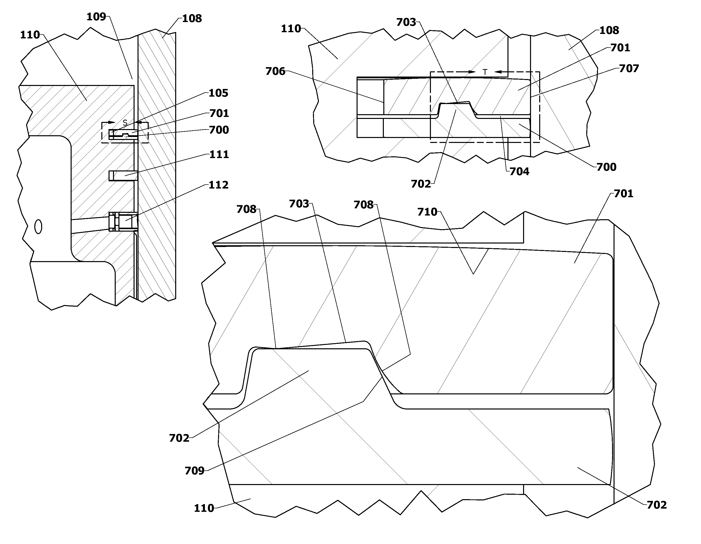
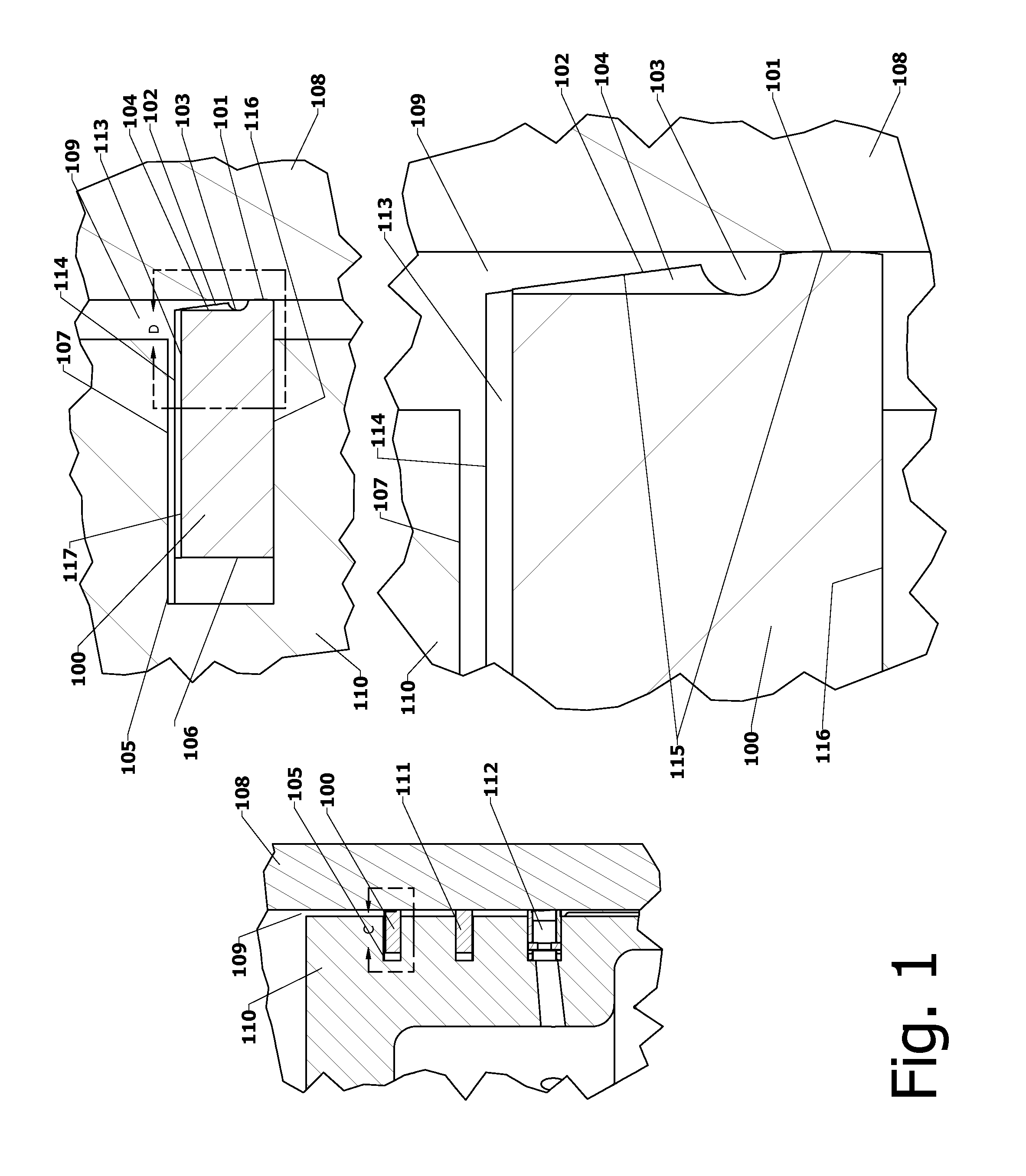
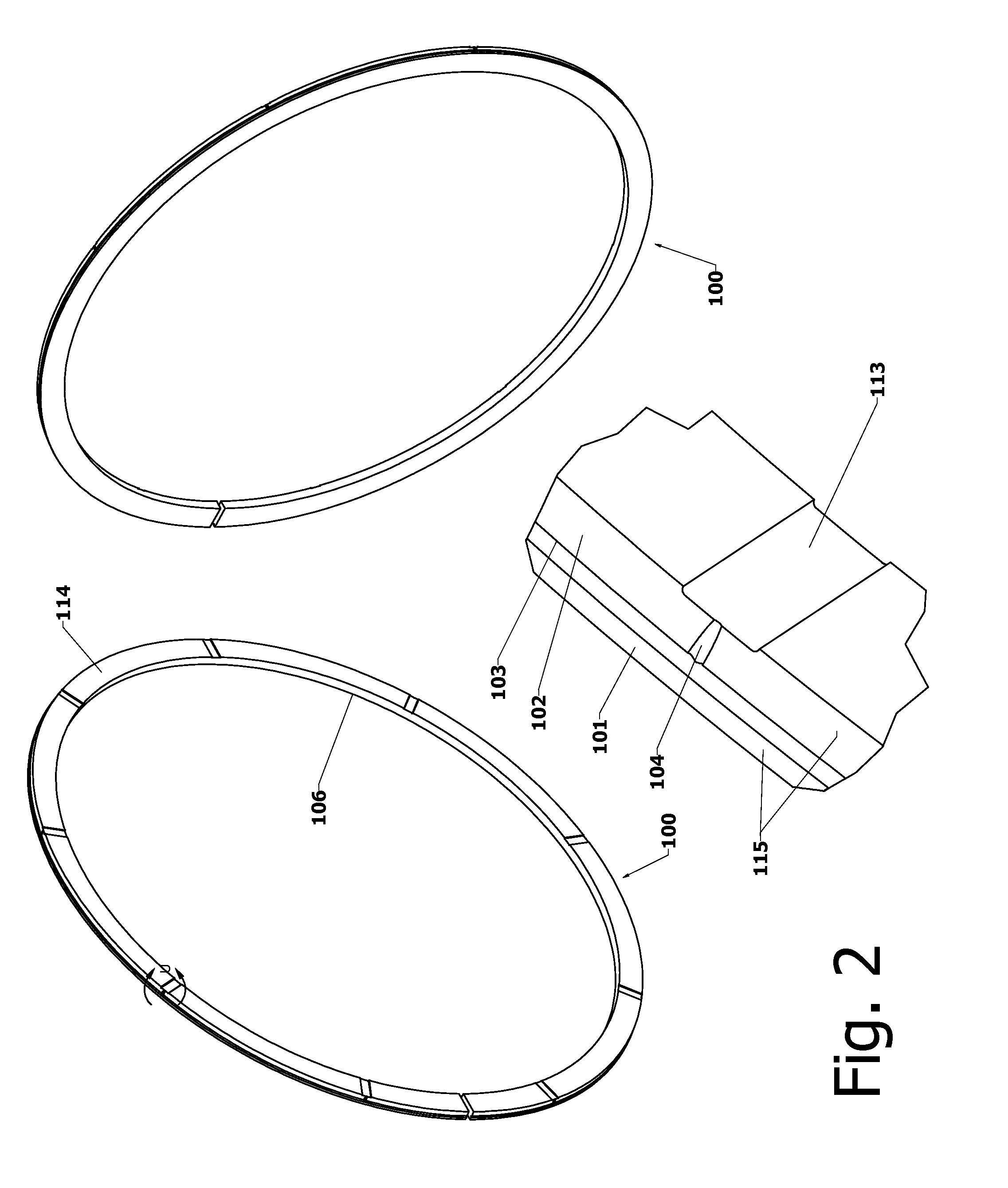
[0026]The prior art and the invention are described with reference to internal combustion engines, but it is to be understood that the invention is applicable to liquid lubricated piston ring gas seals in other applications including gas compressors. In the description “upper”, “top”, “above” and “head” refer to the direction ...


PUM


Abstract

Improved liquid lubricated piston ring gas seals with reduced friction and wear compared to prior art rings are disclosed for use in internal combustion engines, gas pumps, and gas compressors. These improved rings allow independent adjustment of the parameters controlling friction and wear, and eliminate the tradeoff between friction and wear typical of prior art rings.

Description

[0001]This application claims the priority of U.S. provisional application 61 / 744,020.FIELD OF THE INVENTION[0002]The present invention is directed to piston rings that form sliding seals in pistons operating in cylindrical bores, and more particularly relates to liquid lubricated compression rings used as piston gas seals in internal combustion engines and reciprocating pumps and compressors.BACKGROUND OF THE INVENTION[0003]The present invention comprises improvements to the reduced friction piston rings described in Meacham WO / 2009 / 033115, which is incorporated by reference in its entirety.[0004]It is generally known to provide liquid lubricated piston ring seals in reciprocating pistons to reduce gas flow through the diametral clearance between the piston and the bore in which it reciprocates.[0005]Compression rings of the type typically used in internal combustion engines are heat and wear-resistant hard materials such as metal, and may have metallic or ceramic coatings to impro...

Claims


Application Information

Patent Timeline
IPC IPC(8): F16J9/08F16J9/20
CPCF16J9/20F16J9/08F02F5/00F16J9/12
Inventor MEACHAM, G. B. KIRBY
Owner MEACHAM G B KIRBY
Why Eureka
Try Eureka