
Systems and methods for wireless transmission of power

Active Publication Date: 2015-11-12
ENERGOUS CORPORATION
View PDF18 Cites 234 Cited by
  • Summary
  • Abstract
  • Description
  • Claims
  • Application Information

AI Technical Summary

Benefits of technology

The described systems and methods enable wireless power transmitters to communicate with receivers in real-time, allowing for full control and decision-making. The technology also allows multiple BTLE chips to be added to the power transmitter board, enabling simultaneous communication with multiple receivers. This has technical benefits in terms of increased efficiency and flexibility in wireless power transfer.

Problems solved by technology

Such an activity may be tedious and may represent a burden to users.
However, such an activity may render electronic devices inoperable during charging.
Nevertheless, such a solution may still require that electronic devices may have to be placed in a specific place for powering.
Thus, electronic devices during charging may not be portable.
This approach may provide wireless power transmission while eliminating the use of wires or pads for charging devices which may require tedious procedures such as plugging to a wall, and may turn devices unusable during charging.
Although the latter approach may significantly solve the problem of using wires or pads for charging devices, the communication controls among wireless power devices using this approach may demand a real time communication (high transfer rate) and may not be easily achieved.
There are a few off-the-shelf solutions that allow the fast communication between these devices, however these solutions may encounter a limited number of packets sent per second, hence a real time communication may not be reached.

Method used


Image

  • Systems and methods for wireless transmission of power
  • Systems and methods for wireless transmission of power
  • Systems and methods for wireless transmission of power

Examples


Embodiment Construction

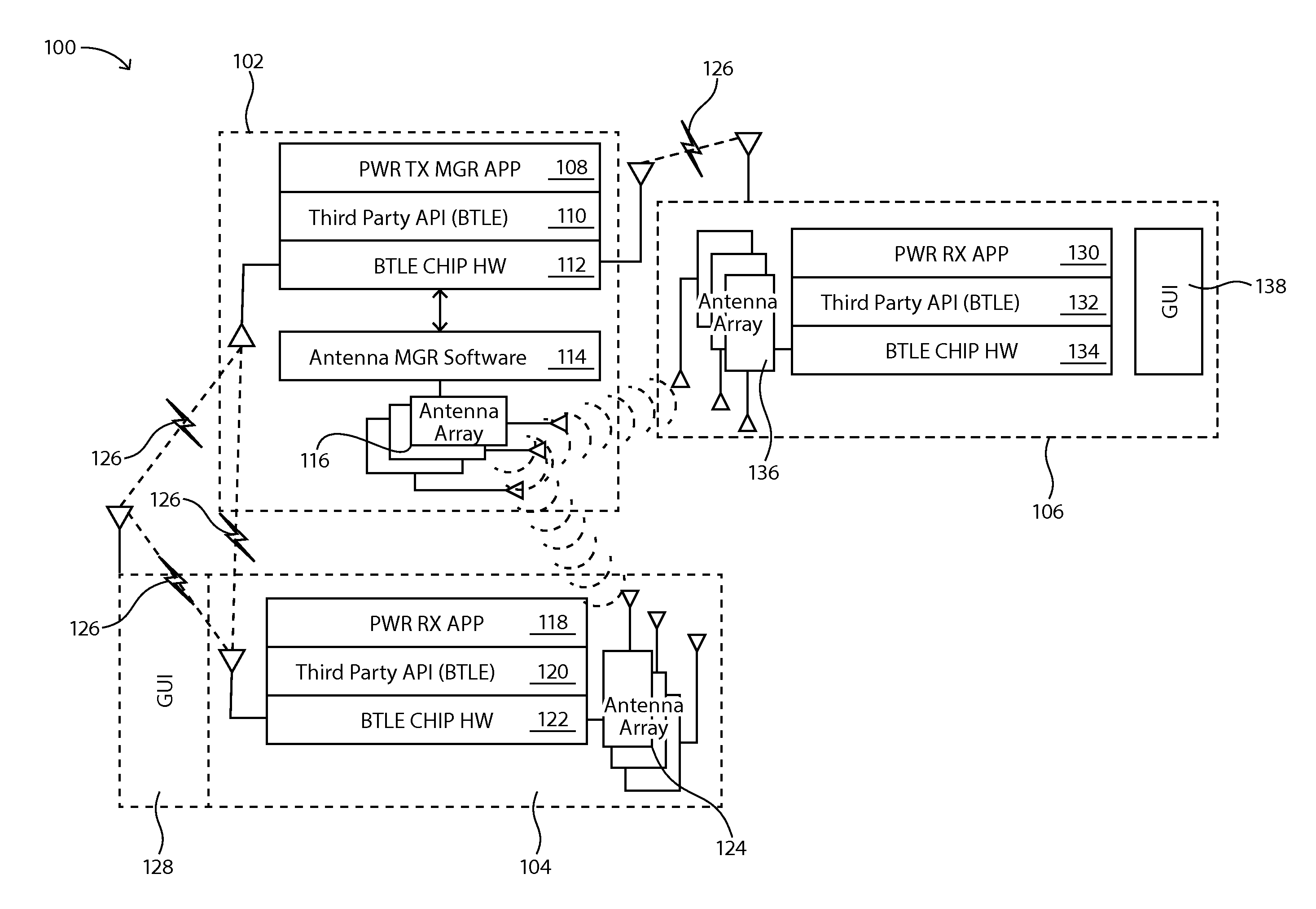
[0021]The present disclosure is here described in detail with reference to embodiments illustrated in the drawings, which form a part here. Other embodiments may be used and / or other changes may be made without departing from the spirit or scope of the present disclosure. The illustrative embodiments described in the detailed description are not meant to be limiting of the subject matter presented here.

DEFINITIONS

[0022]As used here, the following terms may have the following definitions:

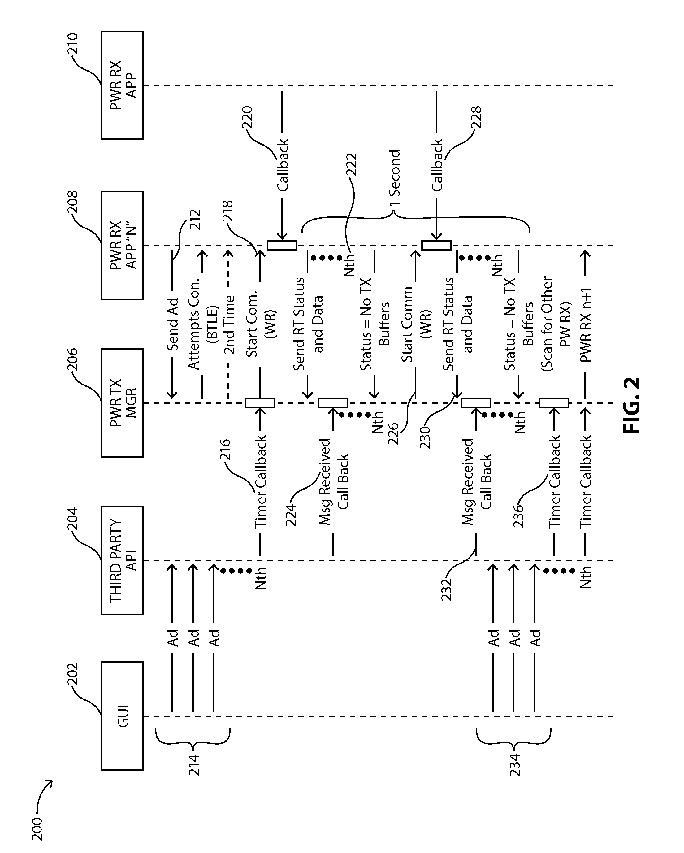
[0023]“Real time communication” refers to communicating the status of data at the receiver at the continuing present time, where a proprietary algorithm may read the present state of important information at the receiver continually and rapidly with only 1 / 100 of a second of delay.

[0024]“Transmitter” may refer to a device, including a chip which may generate two or more RF signals, at least one RF signal being phase shifted and gain adjusted with respect to other RF signals, substantially all of whic...


PUM


Abstract

Systems and methods for real time communication between wireless power transmitters and wireless power receivers based on software embedded on a microprocessor. The systems and methods described here may allow wireless power transmitters to communicate with one or more wireless power receivers in real time within intervals of one second. The systems and methods described here may also enable full control of the wireless power receivers by letting the user decide which wireless power receivers to charge, when to charge them, and set priorities and charging schedules among other functions.

Description

CROSS-REFERENCE TO RELATED APPLICATIONS[0001]The present disclosure is related to U.S. non-provisional patent application DWV-3DPF-010 entitled “Methodology for Pocket-forming”; and DWV-3DPF-028 entitled “Methodology for Multiple Pocket-Forming”; DWV-3DPF-015 entitled “Method for 3 Dimensional Pocket-forming”; DWV-3DPF-027 entitled “Receivers for Wireless Power Transmission”; DWV-3DPF-029 entitled “Transmitters for Wireless Power Transmission,” all of which are invented by Michael Leabman, and all of which are incorporated herein by reference in their respective entireties.BACKGROUND[0002]1. Field of the Disclosure[0003]The present disclosure relates generally to software embedded on a chip, and more specifically to software embedded on a chip that controls the communication between a wireless power transmitter and one or more wireless power receivers in real time.[0004]2. Background Information[0005]Electronic devices such as laptop computers, smartphones, portable gaming devices, ...

Claims


Application Information

Patent Timeline
IPC IPC(8): H02J17/00
CPCH02J17/00H02J50/80H02J50/90H02J50/402H02J50/20
Inventor BELL, DOUGLASLEABMAN, MICHAEL
Owner ENERGOUS CORPORATION
Learn More