
Boost-Charger-Boost System for Enhanced Power Delivery

a technology of booster booster and booster, which is applied in the direction of transmission system, ac network voltage adjustment, transportation and packaging, etc., can solve the problems of limited number of available modes of operation, inability to properly work with low voltage, etc., and achieve the effect of improving functionality

Inactive Publication Date: 2015-11-12
ENERGOUS CORPORATION
View PDF5 Cites 252 Cited by
  • Summary
  • Abstract
  • Description
  • Claims
  • Application Information

AI Technical Summary

Benefits of technology

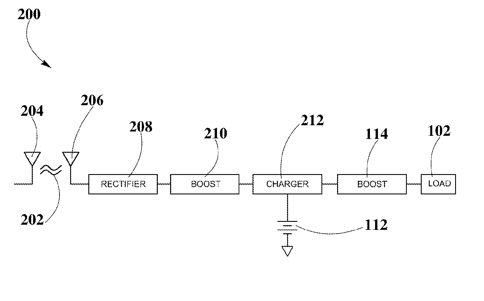
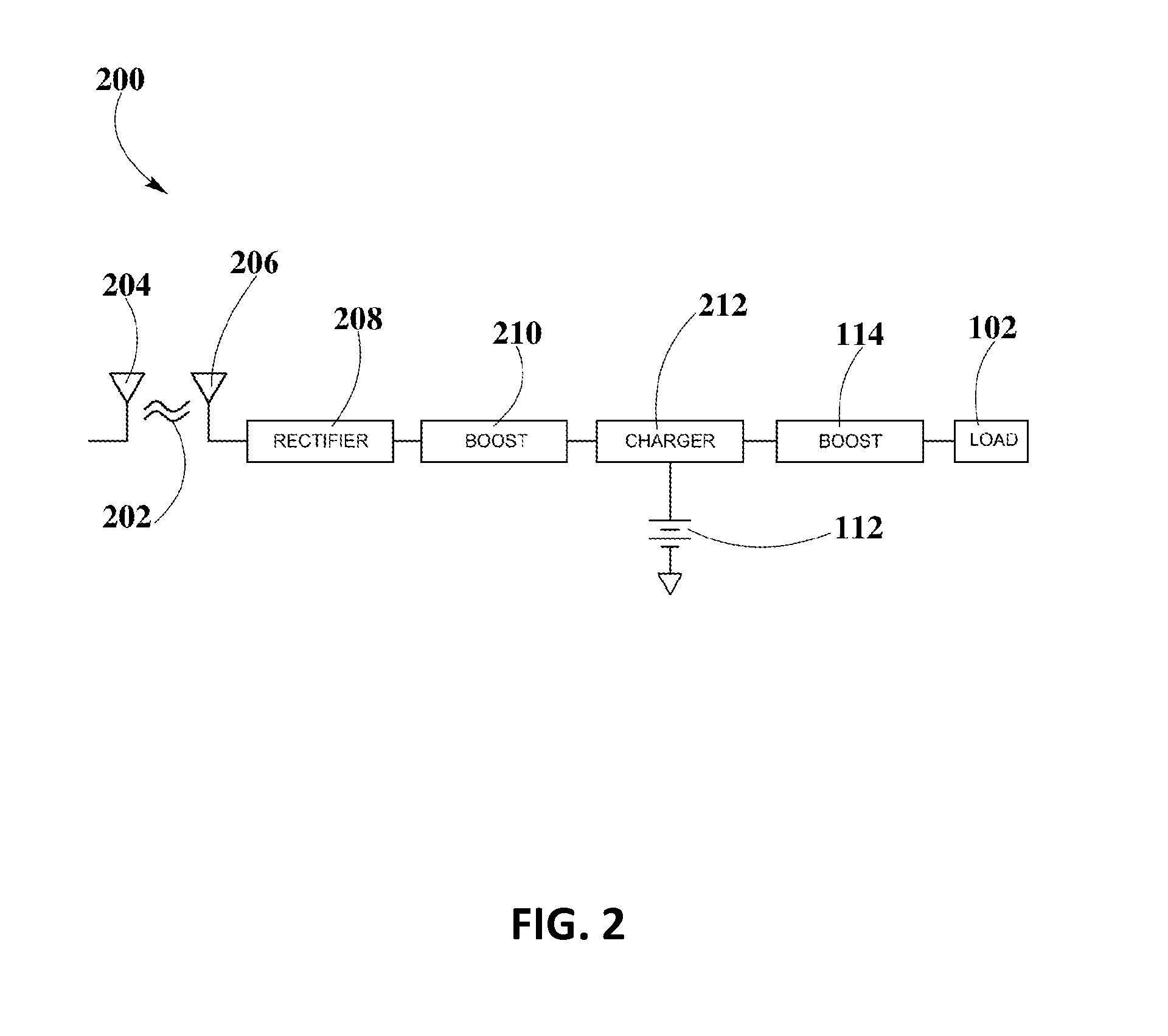
The patent describes a controlled-power delivery system that can use RF waves to deliver continuous and controlled power to a load. The system includes receiving antennas, rectifiers, boost converters, a storage element, and a second boost converter. It can sustain multiple operation modes and has a current conduction path where power can be obtained from either the storage element or the transmitted RF waves. The system can support low voltage power sources and improve function with multiple modes of operation. Overall, the patent provides a technical solution for delivering controlled power to electronic devices using RF waves.

Problems solved by technology

However, these systems may not properly work with low voltage, variable power sources, and they may be limited in terms of the number of available modes of operation.

Method used


Image

  • Boost-Charger-Boost System for Enhanced Power Delivery
  • Boost-Charger-Boost System for Enhanced Power Delivery
  • Boost-Charger-Boost System for Enhanced Power Delivery

Examples


Embodiment Construction

[0023]The present disclosure is here described in detail with reference to embodiments illustrated in the drawings, which form a part here. Other embodiments may be used and / or other changes may be made without departing from the spirit or scope of the present disclosure. The illustrative embodiments described in the detailed description are not meant to be limiting of the subject matter presented here.

DEFINITIONS

[0024]As used here, the following terms may have the following definitions:

[0025]“Pocket-forming” may refer to generating two or more RF waves which converge in 3-d space, forming controlled constructive and destructive interference patterns.

[0026]“Pockets of energy” may refer to areas or regions of space where energy or power may accumulate in the form of constructive interference patterns of RF waves.

[0027]“Null-space” may refer to areas or regions of space where pockets of energy do not form because of destructive interference patterns of RF waves.

[0028]“Transmitter” may...


PUM


Abstract

A controlled-power delivery system may operate with RF waves for supplying continuous and suitable power to a load. The controlled-power delivery system may include one or more receiving antennas, one or more rectifiers, a first boost converter, a charger, a storage element, and a second boost converter. The first boost converter may step up the rectified DC voltage obtained from the receiving antenna and rectifier to supply a suitable voltage level that can be used for charging the storage element. The second boost converter may increase the voltage from the storage element to a suitable level that may satisfy the power requirements of the load. The charger in conjunction with the first and second boost converters may be configured to allow a plurality of modes of operation for delivering power to the load and charging the storage element.

Description

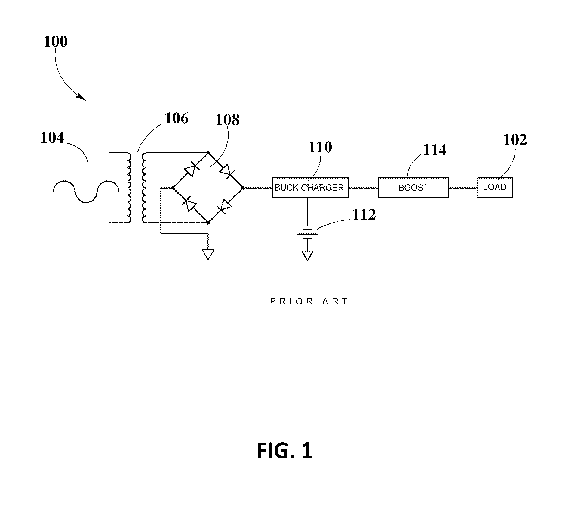
CROSS-REFERENCE TO RELATED APPLICATIONS[0001]The present disclosure is related to U.S. non-provisional patent application DWV-3DPF-010 entitled “Methodology for Pocket-forming”; DWV-3DPF-015 DWV-3DPF-027 entitled “Receivers for Wireless Power Transmission”; and DWV-3DPF-029 entitled “Transmitters for Wireless Power Transmission” invented by Michael Leabman; in addition to ENG-SYHW-001 entitled “Enhanced Receiver for Wireless Power Transmission” invented by Jason Petras and Michael Leabman, each of which are incorporated by reference in their entirety herein.BACKGROUND[0002]1. Field of the Disclosure[0003]The present disclosure relates in general to wireless power transmission, and more specifically, to circuit configurations for obtaining and delivering power from radio frequency (RF) waves.[0004]2. Background Information[0005]Battery-powered systems for delivering continuous and controlled power or voltage to a load may integrate the functions of one buck converter and one boost co...

Claims


Application Information

Patent Timeline
Patent Type & Authority Applications(United States)
IPC IPC(8): H02J17/00H02J7/02
CPCH02J17/00Y10T307/406H02J7/025H02J50/20H02J7/00712
Inventor PETRAS, JASONLEABMAN, MICHAEL
Owner ENERGOUS CORPORATION
Learn More