
Replacement mitral valve with annular flap

a technology of annular flap and mitral valve, which is applied in the field of prosthesis, annuloplasty rings, and replacement mitral valves, can solve the problems of reducing the efficiency of heart blood pumping, debilitating and life-threatening conditions, and inhibiting the valves' ability to control blood flow, etc., and achieves the effect of increasing the surface area of the prosthesis

Inactive Publication Date: 2015-11-19
EDWARDS LIFESCI CARDIAQ
View PDF6 Cites 259 Cited by
  • Summary
  • Abstract
  • Description
  • Claims
  • Application Information

AI Technical Summary

Benefits of technology

The present disclosure is about a prosthesis that can be used to replace a heart valve. It is designed to be deployed within a body cavity and prevent the flow of fluid around it. It consists of an expandable frame and an annular flap positioned around the frame. The frame can radially expand and contract for deployment within the body cavity. The annular flap is secured to the frame and is positioned to create a barrier to fluid flow outside the frame. This helps prevent leaks and other complications during heart valve replacement surgery. The prosthesis can be delivered using a delivery catheter and can be used to treat paravalvular leakage. Overall, this innovation provides a safer and effective way to replace a heart valve.

Problems solved by technology

Diseased heart valves exhibit impairments such as narrowing of the valve or regurgitation, which inhibit the valves' ability to control blood flow.
Such impairments reduce the heart's blood-pumping efficiency and can be a debilitating and life threatening condition.
For example, valve insufficiency can lead to conditions such as heart hypertrophy and dilation of the ventricle.
However, a problem occurs when blood flows around the valve on the outside of the prosthesis.
For example, in the context of replacement heart valves, paravalvular leakage has proven particularly challenging.
An additional challenge relates to the ability of such prostheses to be secured relative to intralumenal tissue, e.g., tissue within any body lumen or cavity, in an atraumatic manner.
Further challenges arise when trying to controllably deliver and secure such prostheses in a location such as at a native mitral valve.

Method used


Image

  • Replacement mitral valve with annular flap
  • Replacement mitral valve with annular flap
  • Replacement mitral valve with annular flap

Examples


Embodiment Construction

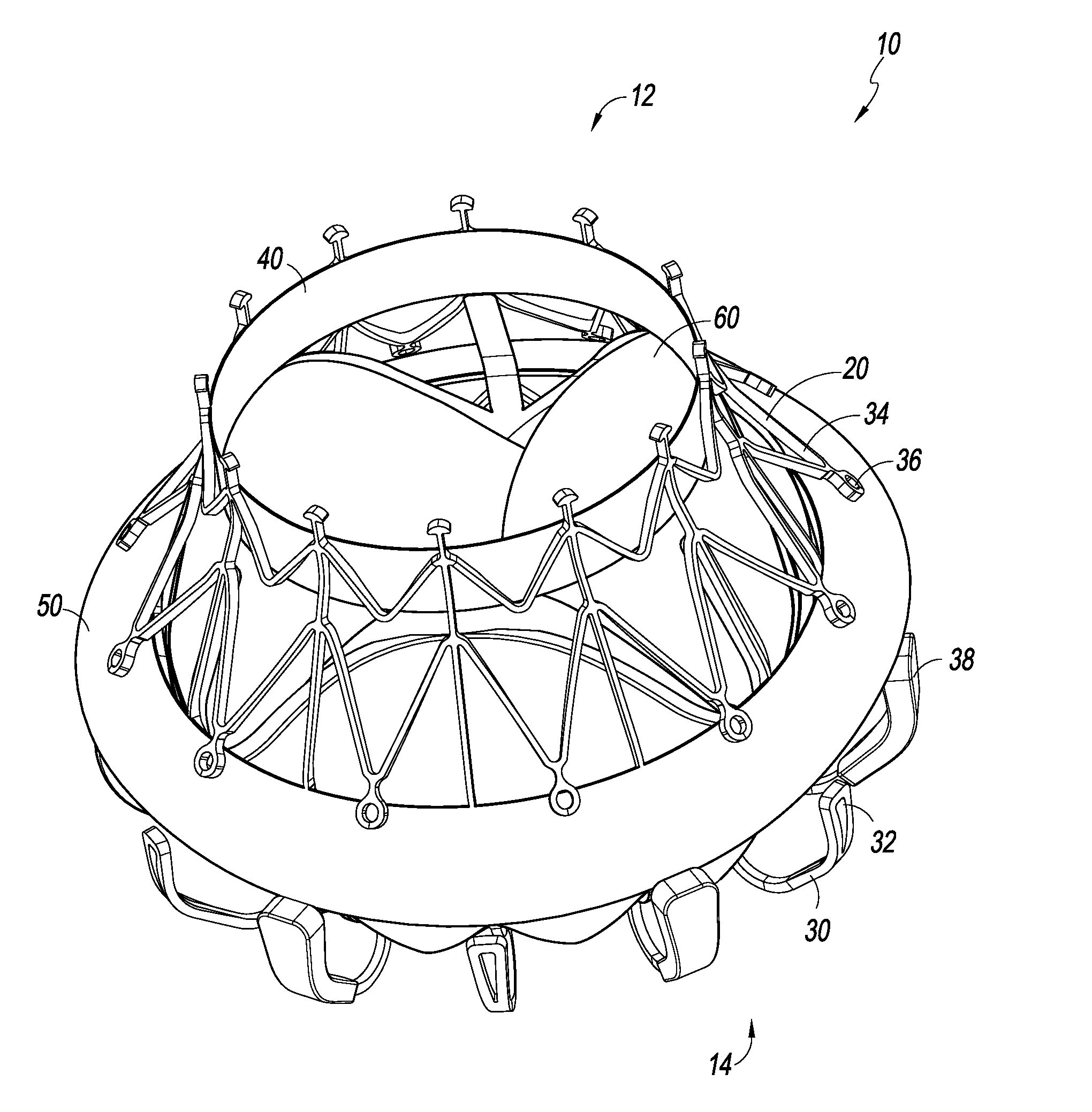
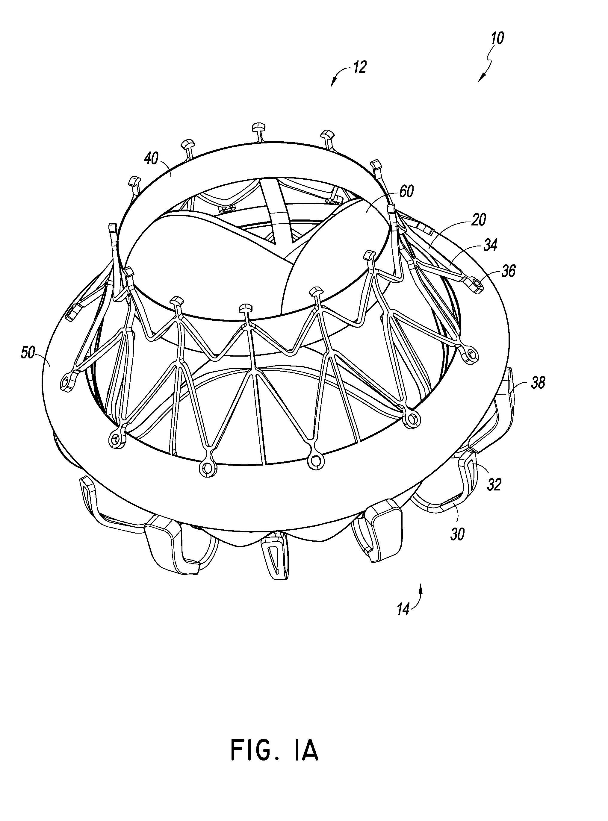
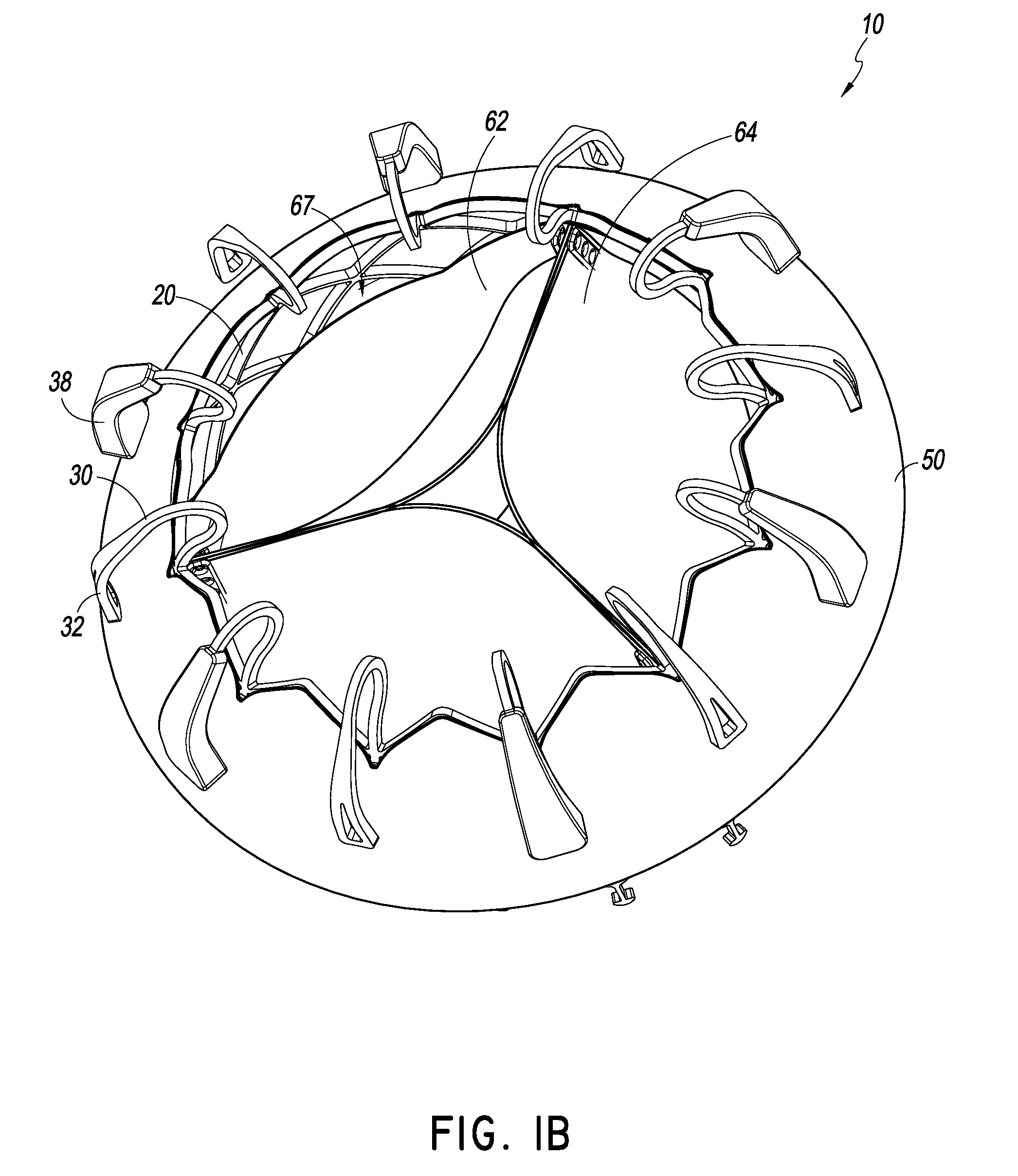
[0026]The embodiment of FIGS. 1A-4 illustrates a prosthesis 10. The prosthesis 10 can have components, features, and / or functionality similar to those described in any of U.S. Publication Nos. 2014 / 0277390, 2014 / 0277422, and 2014 / 0277427, the entire contents of all which are incorporated by reference herein. With reference first to the embodiments of FIGS. 1A-4, the prosthesis 10 can include a frame 20, anchors 30, 34, a band 40, an annular flap or sail 50 and a valve body 60. The prosthesis 10 can include a proximal end 12 and a distal end 14 with openings defined at both ends 12, 14 such that fluid can flow therethrough. In some embodiments, the proximal end 12 can be placed in the left atrium while the distal end 14 can be placed in the left ventricle such that prosthesis 10 can function as a replacement for a mitral valve. As will be discussed in greater detail below and as discussed in U.S. Publication Nos. 2014 / 0277390, 2014 / 0277422, and 2014 / 0277427, the prosthesis 10 can all...


PUM


Abstract

A prosthesis can be configured to grasp intralumenal tissue when deployed within a body cavity and prevent axial flow of fluid around an exterior of the prosthesis. The prosthesis can include an expandable frame configured to radially expand and contract for deployment within the body cavity, and an annular flap positioned around an exterior of the expandable frame. In some embodiments, the annular flap can extend outward from the frame and have a collapsed configuration and an expanded configuration.

Description

CROSS-REFERENCE TO RELATED APPLICATIONS[0001]This application claims priority to U.S. Provisional App. No. 62 / 000,309 filed May 19, 2014, titled REPLACEMENT MITRAL VALVE WITH ANNULAR FLAP, which is hereby incorporated herein by reference in its entirety and is to be considered a part of this specification.BACKGROUND[0002]1. Field[0003]Certain embodiments disclosed herein relate generally to prostheses for implantation within a lumen or body cavity. In particular, certain embodiments relate to expandable prostheses such as replacement heart valves, such as for the mitral valve, that are configured to atraumatically grasp intralumenal tissue.[0004]2. Background[0005]Human heart valves, which include the aortic, pulmonary, mitral and tricuspid valves, function essentially as one-way valves operating in synchronization with the pumping heart. The valves allow blood to flow downstream, but block blood from flowing upstream. Diseased heart valves exhibit impairments such as narrowing of t...

Claims


Application Information

Patent Timeline
IPC IPC(8): A61F2/24
CPCA61F2/2445A61F2/2418A61F2250/0069A61F2220/0008A61F2220/005A61F2220/0075A61F2250/0039
Inventor RATZ, J. BRENTPESCE, LUCARABITO, GLENNGUYEN, CHRISTINE THANH
Owner EDWARDS LIFESCI CARDIAQ
Learn More