
Control device for 4wd vehicle

a technology for controlling devices and vehicles, applied in control devices, driver input parameters, vehicle components, etc., can solve problems such as no technology for improving control responsiveness, and achieve the effect of suppressing shift control delay and prompting and continuous increas

Active Publication Date: 2015-11-19
TOYOTA JIDOSHA KK
View PDF7 Cites 16 Cited by
  • Summary
  • Abstract
  • Description
  • Claims
  • Application Information

AI Technical Summary

Benefits of technology

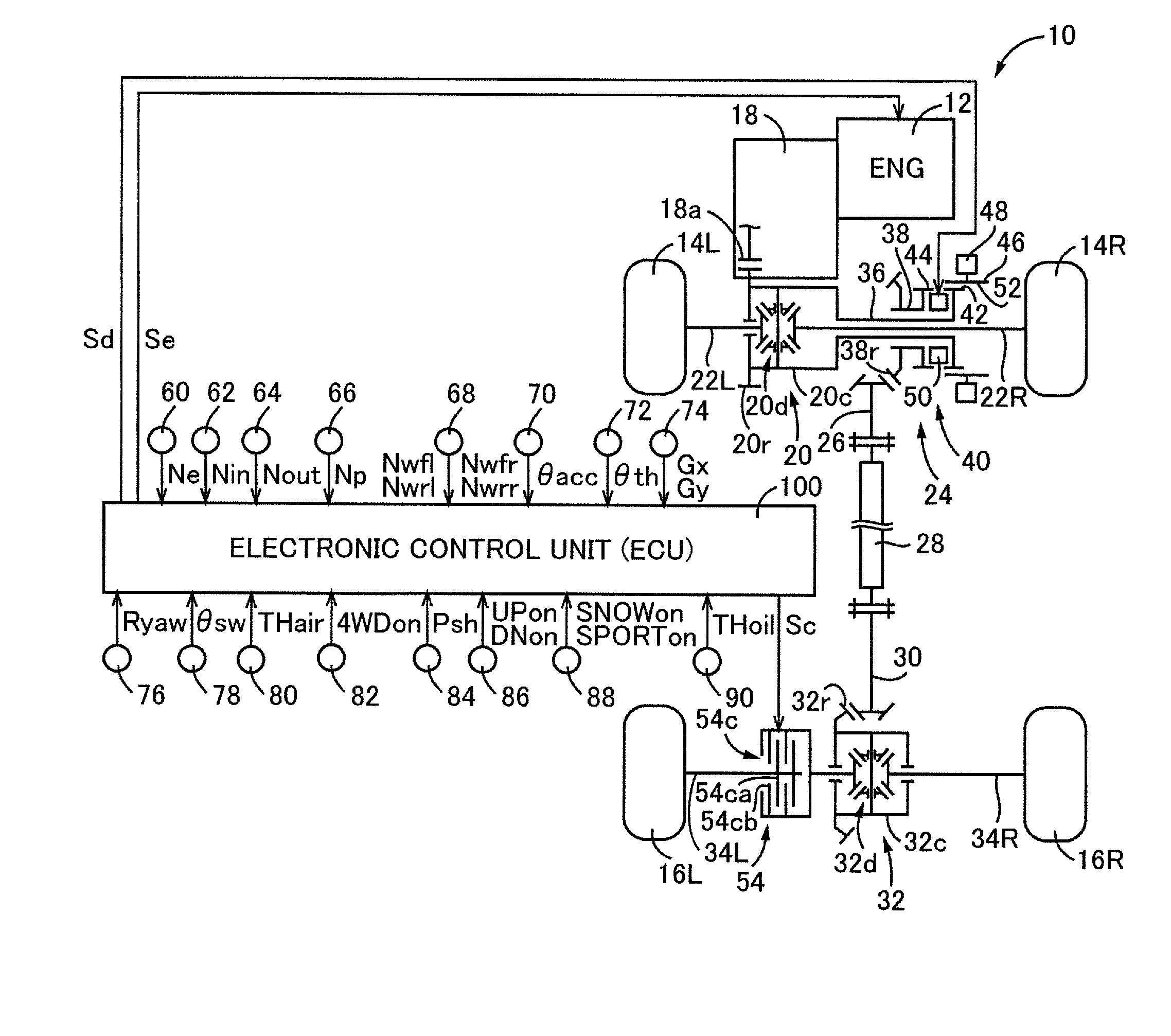
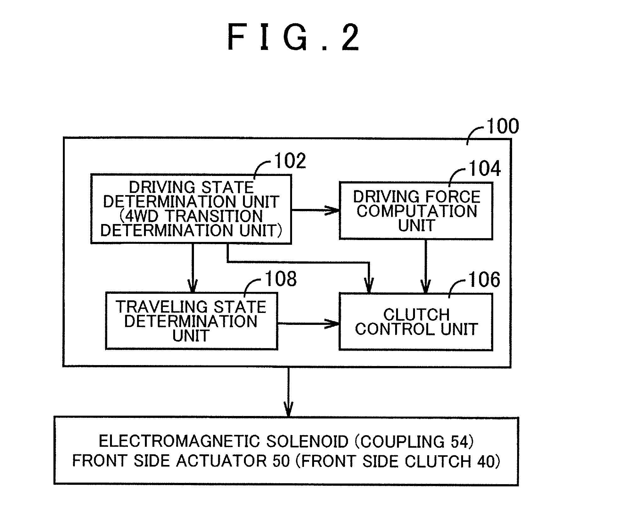
The invention is a control device for a 4WD vehicle that improves the responsiveness of control for transition from 2WD traveling to 4WD traveling. The electronic control unit determines when to transition from 2WD to 4WD based on the vehicle's traveling state and engagement force of the clutch. This results in a quick and continuous increase in the driving force transmission shaft's rotation speed, reducing delay in shifting and improving overall control.

Problems solved by technology

Also, no technique has been proposed with regard to improving the responsiveness of control after the moment when the transition from 2WD traveling to 4WD traveling becomes essential.

Method used


Image

  • Control device for 4wd vehicle
  • Control device for 4wd vehicle
  • Control device for 4wd vehicle

Examples


first embodiment

[0073]In this embodiment, the traveling state determination unit 108 determines whether or not the vehicle 10 is in the predetermined traveling state, based on whether or not the operation is performed by the driver, in Steps corresponding to S40 and S50 in the flowchart that is illustrated in FIG. 3A for the first embodiment described above. In addition, the driving state determination unit 102 determines whether or not to perform transition to 4WD traveling by determining whether or not the shift of the transmission 18 is initiated in Step corresponding to S110 in the flowchart that is illustrated in FIG. 3B.

[0074]As described above, effects similar to those of the first embodiment can be achieved by this embodiment. In addition, in the traveling state where the shift of the transmission 18 is likely to be executed and transition to 4WD traveling is preferable, the engagement force in controlling the engagement force of the coupling 54 can be controlled to be the engagement force ...

second embodiment

[0082]In the embodiments described above, various automatic transmissions such as a planetary gear-type multi-speed transmission, a continuously variable transmission, and a synchromesh-type parallel two-shaft transmission (including a known DCT) have been described as examples of the transmission 18. However, the invention is not limited thereto. For example, the transmission 18 may be a known manual transmission or the transmission 18 is inessential insofar as the aspect of performing the control for transition to 4WD traveling is not executed in accordance with the shift of the transmission 18 as in the second embodiment described above.

[0083]In the embodiments described above, the vehicle 10 is provided with the paddle switch 86 (manual transmission device) and the traveling mode selection switch 88. However, the invention is not limited thereto. For example, at least any one of the paddle switch 86 (manual transmission device) and the traveling mode selection switch 88 may be p...


PUM


Abstract

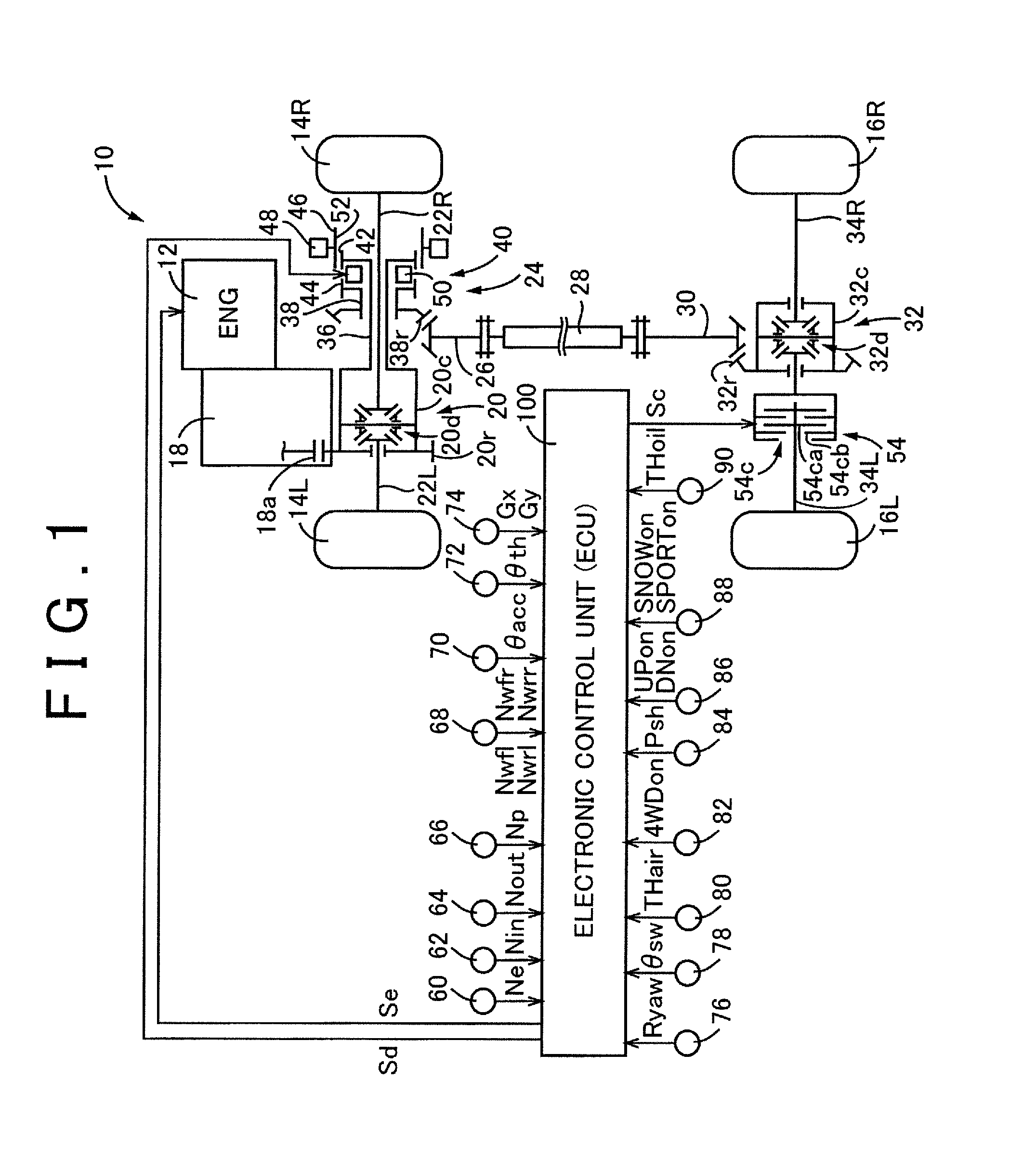
Control device for a 4WD vehicle is provided. The 4WD vehicle includes a driving force source, main driving wheels, auxiliary driving wheels, a driving force transmission shaft, a first disconnection mechanism, and a second disconnection mechanism. The first disconnection mechanism and the second disconnection mechanism are engaged during 4WD traveling. One of the first disconnection mechanism and the second disconnection mechanism is a clutch. The control device includes an electronic control unit. The electronic control unit is configured to execute engagement control for controlling the engagement force of the clutch so that the driving force transmission shaft is maintained in a state prior to the initiation of a continuous increase in the rotation speed of the driving force transmission shaft.

Description

INCORPORATION BY REFERENCE[0001]The disclosure of Japanese Patent Application No. 2014-100024 filed on May 13, 2014 including the specification, drawings and abstract is incorporated herein by reference in its entirety.BACKGROUND OF THE INVENTION[0002]1. Field of the Invention[0003]The invention relates to a control device that switches operation states of two disconnect mechanisms in accordance with a traveling state of a 4WD vehicle. The two disconnect mechanisms are two disconnection mechanisms that are disposed on a driving force source side and an auxiliary driving wheels side of a driving force transmission shaft, respectively.[0004]2. Description of Related Art[0005]4WD vehicles that are provided with two disconnection mechanisms as disconnect mechanisms are widely known. The two disconnection mechanisms are disposed on a driving force source side and an auxiliary driving wheels side of a driving force transmission shaft (for example, propeller shaft), respectively. The drivi...

Claims


Application Information

Patent Timeline
IPC IPC(8): B60K23/08
CPCB60K2023/0858B60K23/08B60K17/3515B60K23/0808B60W50/082B60W2520/10B60W2520/14B60W2520/263B60W2540/16B60W2710/02B60W2710/1038B60W2710/125B60W10/14B60W10/119B60W2540/215
Inventor TAKAIRA, KOJIIWATSUKI, KUNIHIROISHII, HIROYUKI
Owner TOYOTA JIDOSHA KK
Learn More