Window System

a technology applied in the field of windows, can solve the problems of compromising the integrity of materials and purposes, affecting the quality of windows, and affecting the quality of windows, and achieving the effect of improving the quality of windows and doors, and reducing the cost of improved products

Active Publication Date: 2015-11-19
NEWTONOID TECH L L C
View PDF3 Cites 16 Cited by
  • Summary
  • Abstract
  • Description
  • Claims
  • Application Information

AI Technical Summary

Benefits of technology

[0004]The following presents a simplified summary of the invention in order to provide a basic understanding of some aspects of the invention. This summary is not an extensive overview of the invention. It is not intended to identify critical elements of the invention or to delineate the scope of the invention. Its sole purpose is to present some concepts of the invention in a simplified form as a prelude to the more detailed description that is presented elsewhere.

Problems solved by technology

Impact forces received upon particular materials may compromise the integrity of the material and the purpose for which it is used.
However, glass products such as automobile windshields and home windows are particularly prone to encounter debris that may result in some degree of cracking, chipping, or even shattering (collectively “breakage”).
While manufacturing advancements have been made to improve the resilience of glass products, such improved products may be undesirably expensive and may nevertheless still be susceptible to breakage.
Further, those manufacturing advancements do not aid existing products that were made with older technology.

Method used


Image

  • Window System
  • Window System
  • Window System

Examples


embodiment 100

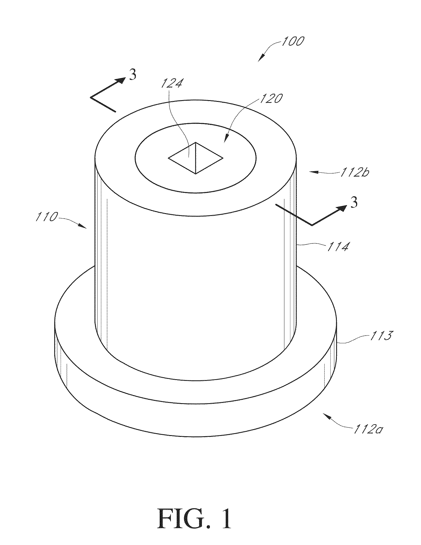
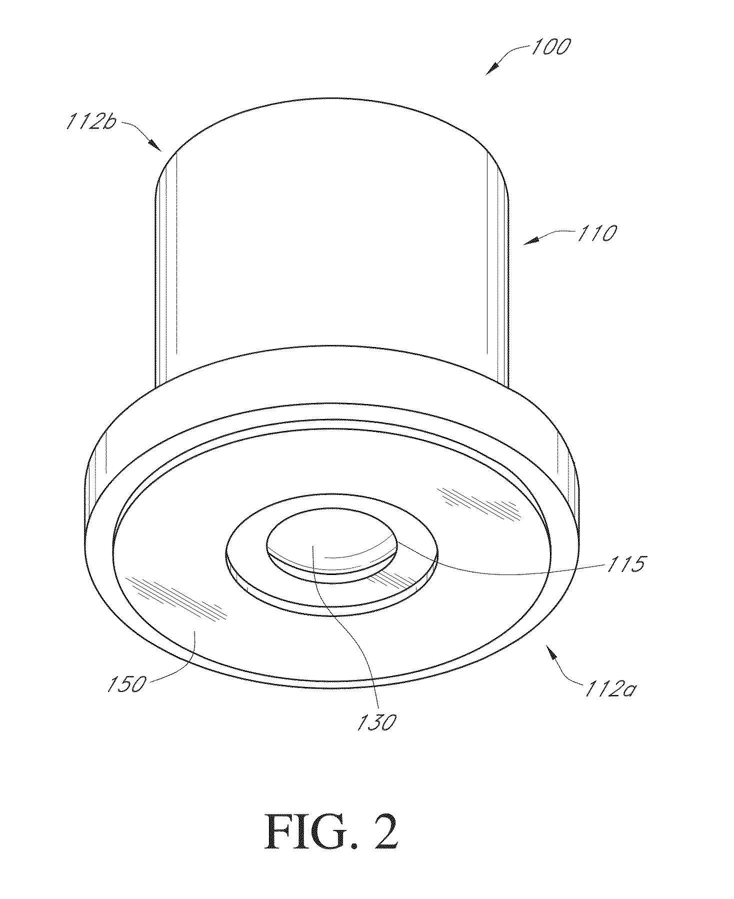
[0065]The housing 110 has a contact end 112a opposite a distal end 112b, and the contact end 112a has an aperture 115 (FIGS. 2 through 4). While the housing 110 may be configured in various ways, it may be desirable for the contact end 112a to have a surface area that is greater than a surface area of the distal end 112b. Such increased surface area at the contact end 112a may allow the housing 110 to be better coupled to a glass surface (as discussed further below) while minimizing the size of the housing 110 at the distal end 112b. The housing 110 is shown to have a first portion 113 extending from the contact end 112a and a second portion 114 extending from the distal end 112b, with each portion 113, 114 being generally cylindrical and extending to one another. While such configuration is currently preferred in the embodiment 100, other geometries (conical, rectangular, octagonal, irregular geometries, more or fewer portions, et cetera) may nevertheless be used.

[0066]The housing ...

embodiment 200

[0078]In embodiment 200, endcap 220 is fused to housing 210. For example, the housing 210 and the endcap 220 may be plastic coupled together through friction welding or ultrasonic welding.

[0079]FIGS. 8 through 11 show another apparatus 300 for inhibiting glass breakage that is substantially similar to the embodiment 100, except as specifically noted and / or shown, or as would be inherent. Further, those skilled in the art will appreciate that the embodiment 100 (and thus the embodiment 300) may be modified in various ways, such as through incorporating all or part of any of the various described embodiments, for example. For uniformity and brevity, reference numbers between 300 and 399 may be used to indicate parts corresponding to those discussed above numbered between 100 and 199 (e.g., housing 310 corresponds generally to the housing 110), though with any noted or shown deviations.

[0080]In embodiment 300, the housing 310 is sized to contain more than one of the contact members 330...

embodiment 300

[0081]The contact members 330 are disposed at least primarily inside the housing 310, with each of the contact members 330 being associated with (and biased toward) a respective aperture 315. The embodiment 300 includes rectangular contact members 330 each having a recess 331 (FIG. 11), and the apertures 315 are smaller than the contact members 330 such that the contact members 330 cannot completely pass through the apertures 315. Such sizing may be particularly desirable when the apparatus 300 is for “aftermarket” use (i.e., when the glass product is not sold with the apparatus 300).

[0082]When multiple contact members 330 are included, they may be biased toward the apertures 315 by a single biasing member 340, or by multiple biasing members 340. The embodiment 300 includes multiple biasing members 340, shown to be flat springs 340a coupled to one another by a rail 340b. More particularly, the embodiment 300 includes a piece of stamped metal bent to define the flat springs 340a. Whi...


PUM


Abstract

A window system is disclosed. The window system includes a window which has a first window pane spatially separated from a second window pane. The window panes are surrounded by a window frame, which houses a memory device for storing electronic data.

Description

CROSS-REFERENCE TO RELATED APPLICATIONS[0001]This application is a continuation-in-part of U.S. patent application Ser. No. 14 / 528,099, filed Oct. 30, 2014, which claims priority to U.S. Provisional Patent Application No. 62 / 928,687, filed Jan. 17, 2014 and is also a continuation-in-part of U.S. patent application Ser. No. 14 / 310,899, filed Jun. 20, 2014, now U.S. Pat. No. 8,899,562, issued Oct. 2, 2014; which claims priority to U.S. Provisional Patent Application No. 61 / 988,024, filed May 2, 2014 and is also a continuation-in-part of U.S. patent application Ser. No. 14 / 188,303, filed Feb. 24, 2014, now U.S. Pat. No. 8,789,818, issued Sep. 29, 2014, which is a continuation-in-part of U.S. patent application Ser. No. 13 / 796,170, filed Mar. 12, 2013, now U.S. Pat. No. 8,695,955, issued Apr. 15, 2014. All of the aforementioned are incorporated herein by reference in their entireties.BACKGROUND[0002]Impact forces received upon particular materials may compromise the integrity of the mat...

Claims


Application Information

Patent Timeline
Patent Type & Authority Applications(United States)
IPC IPC(8): E06B5/12G05D23/19F16F1/04H05B3/84E06B3/66E06B5/11
CPCE06B5/12E06B3/6604G05D23/1917F16F1/04H05B3/84E06B5/11E06B3/68
Inventor STATON, FIELDING B.
Owner NEWTONOID TECH L L C
Why Eureka
Try Eureka