System and method for cleaning submersible motor pumps covered with suction sleeves and disposed horizontally or vertically

Active Publication Date: 2015-11-19
ABBRUZZESE PERMUTT GINO ROCCO
View PDF0 Cites 2 Cited by
  • Summary
  • Abstract
  • Description
  • Claims
  • Application Information

AI Technical Summary

Benefits of technology

The present invention is a cleaning system for submersible motor pumps with suction sleeves or water tubing. The system is designed to solve problems of obstruction, premature wear, and increased energy consumption caused by sediments and impurities in the water. The cleaning system can be used in various forms and can be installed in different ways, such as horizontal or vertical. It allows submersible pumps to operate with water from different sources and qualities, improving their performance and reducing maintenance costs. The cleaning system can be easily disassembled for cleaning and reassembly, and it allows for more frequent cleaning of the pumps, improving their longevity and reducing energy consumption.

Problems solved by technology

All this causes more wearing and operative difficulty, such as obstruction or adherence, which prevents proper rotation, especially of the impellers of submersible motor pumps.
With greater wearing and difficulty to operate these elements, inadequate functioning is produced of the motor pumps and, as a consequence, increased energy demand.
Therefore, also occurs a higher cost for maintenance, cost versus benefit ratio deteriorates and mainly reduces the useful life span of submersible motor pumps.
However; no background exist of utilizing during cleaning of submersible pumps, covered suction sleeves, cleaning products and soaking motor pumps for a time, with these chemicals, in the place where these pumps operate.
Normally submersible motor pumps, are disposed forming part of large industrial pump equipment, either in the mining industry, agriculture, potable water, in urban or rural medium, public and private buildings; hospital, industrial, hotel, sports and tourism developments, arranged horizontally or vertically, above or under the ground and on complex or sophisticated equipment and sometimes non operative, because it cannot be suspend in many cases, production processes and other cases due to the large distances to the control centers.
Therefore, periodically disassembly the submersible motor pumps for performing maintenance and cleaning is expensive and often inoperative.

Method used


Image

  • System and method for cleaning submersible motor pumps covered with suction sleeves and disposed horizontally or vertically
  • System and method for cleaning submersible motor pumps covered with suction sleeves and disposed horizontally or vertically
  • System and method for cleaning submersible motor pumps covered with suction sleeves and disposed horizontally or vertically

Examples


Embodiment Construction

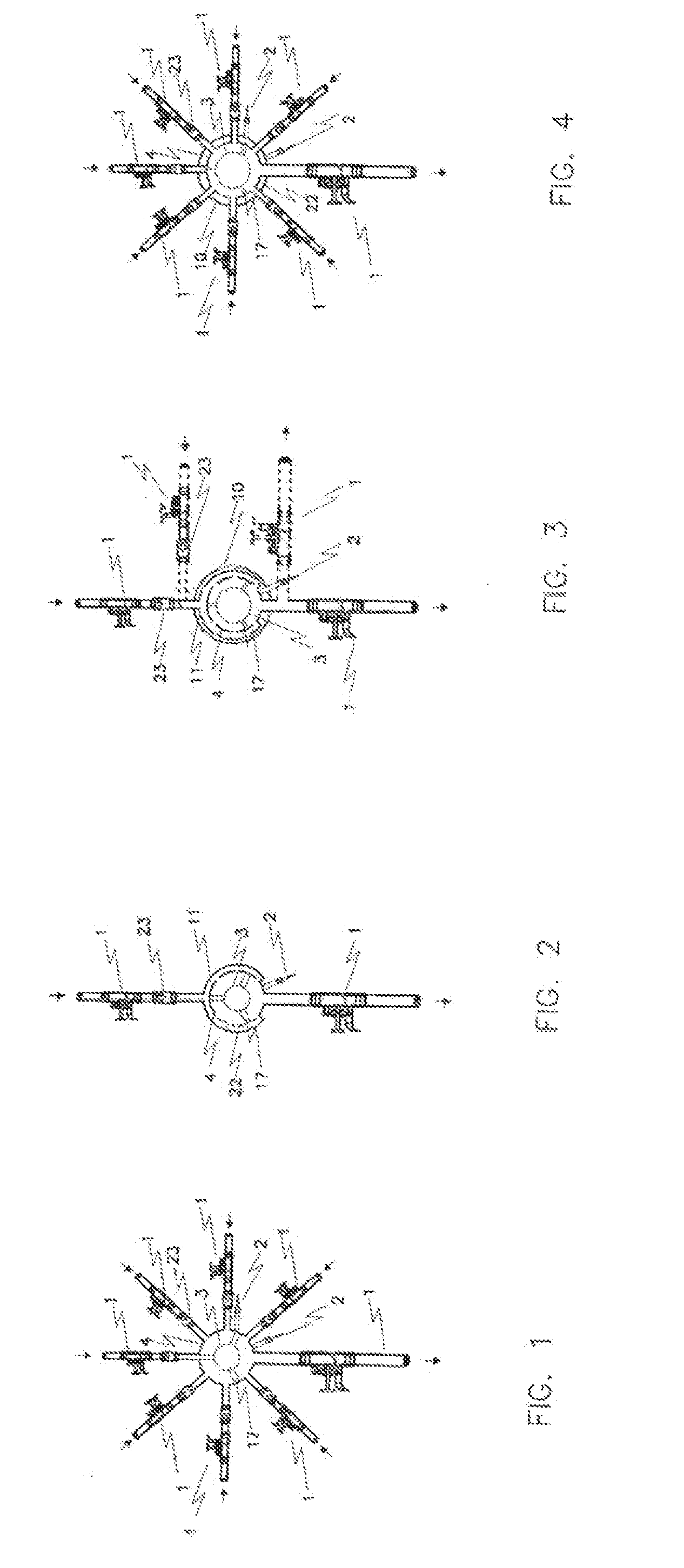
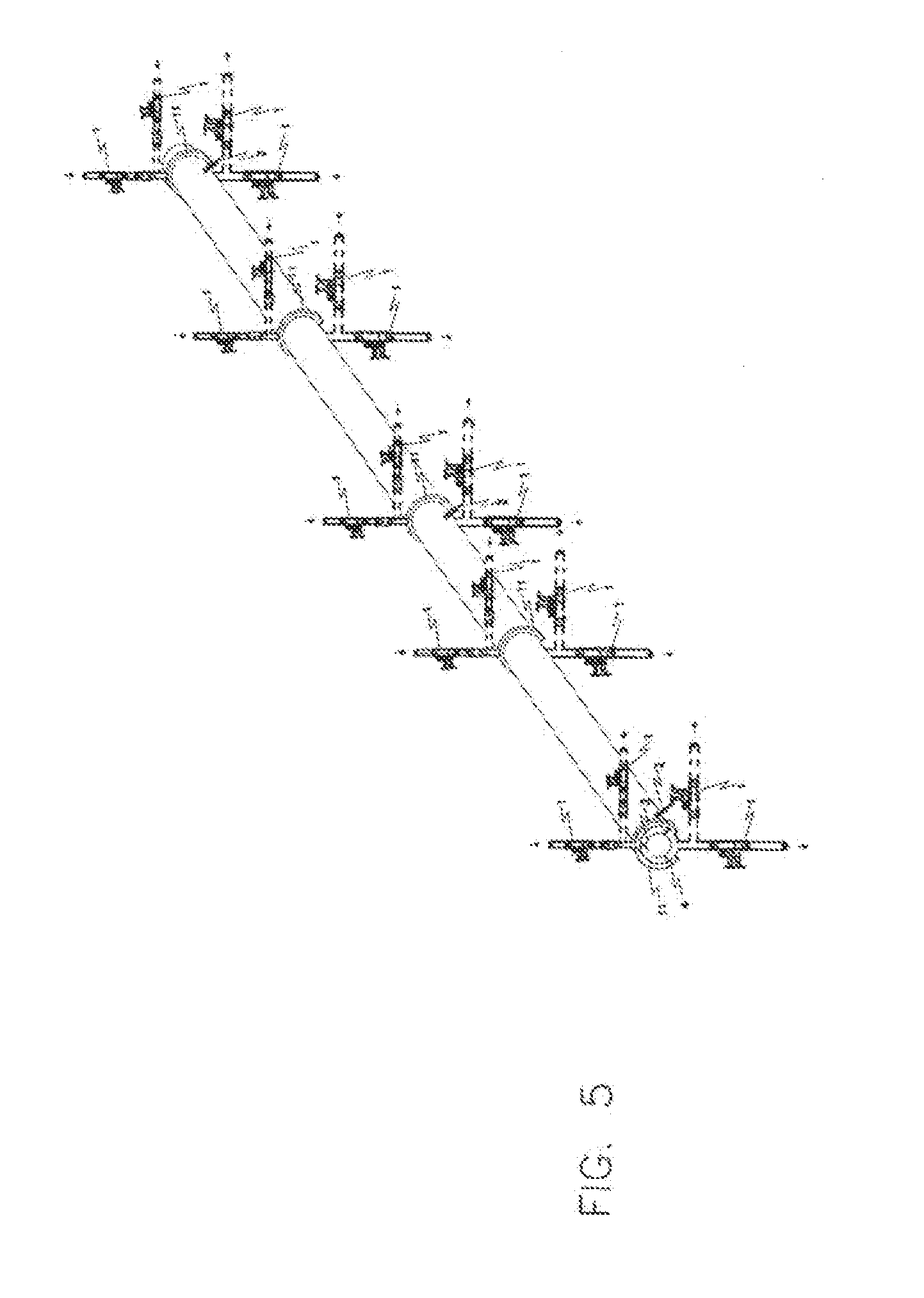
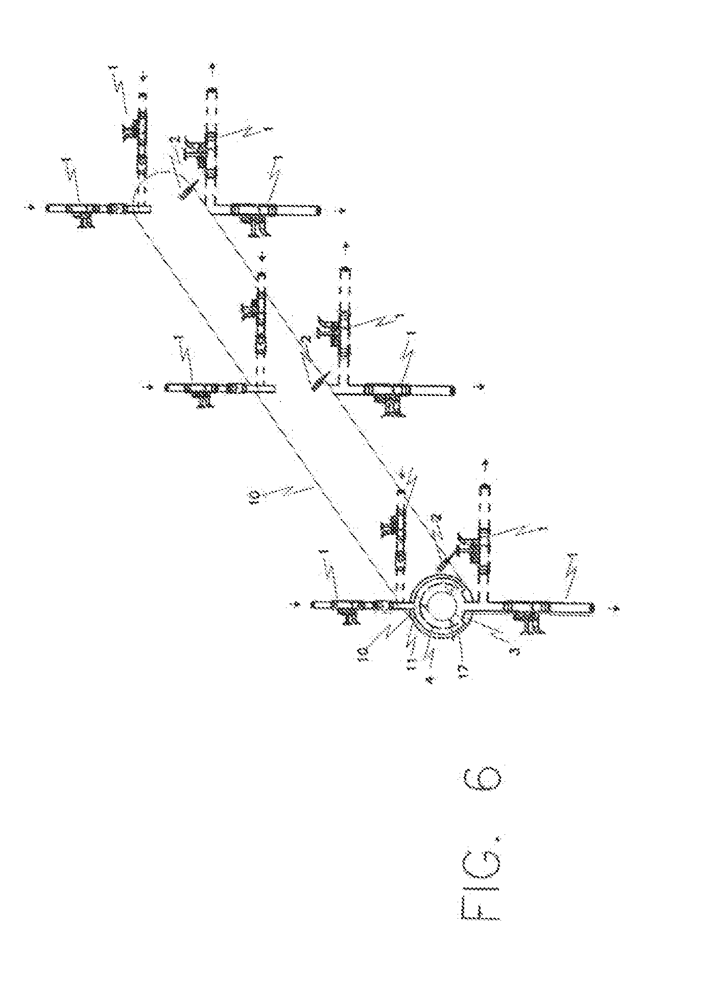
[0060]The invention corresponds to a set of valves (1) and sensors (2) placed in several zones, in different spatial arrangement (FIG. 1, 2, 3, 4, 5, 6, 7), and in different places of the submersible motor pumps (3), covered with suction sleeves (4), arranged horizontally (FIG. 8, 9, 10) or vertically (FIG. 11).

[0061]The present invention consists in a cleaning system which provides basically a series of valves (1) of different types and operation, and sensors (2) which can be individual or multi-parametric, that is, on a single device may be disposed several sensors which detect or measure different parameters, for example, pressure, electrical conductivity, hardness, chlorine detectors, detergent, arranged in the three zones (FIG. 8, 11) of the submersible motor pumps (3), covered with suction sleeves (4). These zones are defined primarily as A, impeller zone (14), zone B, motor zone (15) and zone C, central, where the suction filter (16) is located. Valves and sensors are also lo...


PUM


Abstract

The invention relates to a cleaning system for submersible motor pumps (3) covered with suction sleeves and disposed horizontally or vertically. The system comprises sensors and a series of ducts for injecting water and cleaning compounds, disposed in the suction sleeve (4) of the pump in three zones, namely: an impeller zone A, a motor zone B and a central suction filter (16) zone C. The system can be applied to two submersible pumps in parallel, each pump driving the injection liquids of the other. The used method comprises five steps: a first step comprising the consecutive washing of zones A, B and C; a second step comprising the injection of cleaning compounds; a third soaking step; a fourth step comprising the consecutive heavy-duty washing of zones A, B and C; and a fifth step corresponding to the end of the method.

Description

FIELD OF THE INVENTION[0001]The present invention was conceived as a solution to solve basically problems of obstruction, premature wearing, reduction on the lifespan, malfunctioning y higher energy consume, due to the presence of sediments and impurities present in the water and adhered to the mobile and fixed parts of submersible motor pumps covered with suction sleeves, which are in direct contact with the water. The invention corresponds to a cleaning system, for submersible motor pumps, covered with suction sleeves or water tubing, disposed in horizontal or vertical form, above or under the ground, inside empty chambers, without water, or inside tanks with water or inside general common tubing, and comprises series of valves and sensors, disposed in three zones defined as A, impellers, B, motor, C, central of suction filter. The valves and sensors are disposed on, in the sides or under the suction sleeves and also in the suction and discharge pipes, connection flange, of the su...

Claims


Application Information

Patent Timeline
IPC IPC(8): F04D29/70F04D13/08
CPCF04D13/08F04D29/708E21B37/00F04D13/10F04D13/14
Inventor ABBRUZZESE PERMUTT, GINO ROCCO
Owner ABBRUZZESE PERMUTT GINO ROCCO
Why Eureka
Try Eureka