Vacuum suction cup having bowl-shaped framework

a vacuum cavity and suction cup technology, applied in the field of vacuum cavity suction cups, can solve the problems of limited recovery tendency, achieve the effect of enhancing the sealing effect of the vacuum cavity, facilitating the running of molding materials, and insufficient strength

Active Publication Date: 2015-11-19
ZHONGSHAN TAILI HOUSEHOLD PROD MFG
View PDF3 Cites 17 Cited by
  • Summary
  • Abstract
  • Description
  • Claims
  • Application Information

AI Technical Summary

Benefits of technology

[0034](3) In the invention, radial cuts are used to deform the framework when pressed, and to facilitate the running of molding materials during a secondary injection in forming the cup and hence the fully wrapping of the framework by the soft material, make the framework an integral part of the cup body. Furthermore, the individual fragments formed due to the radial cuts can perform the “grasping” act, similar to the fingers of the human palm. In particular, on uneven, coarse, dense, and airtight supporting surfaces, each of the fragments can be adsorbed to an area with different characteristics, such as height, of the actual supporting surface, realizing automatic adaption to an uneven supporting surface. Therefore, the suction cup of the present invention are particularly suitable for uses on uneven, coarse, dense, and airtight supporting surfaces.
[0035](4) Alternate arrangement of short and long cuts of the framework can ensure the strength of each Y-shaped fork to overcome insufficient strength provided by small individual fragments due to the presence of the cuts.
[0036](5) The seals can further enhance sealing effect of the vacuum cavity, increasing adsorptive force of the suction cup as well as forming a friction surface between seals and edge of cup body, thus ensuring a sufficient vacuum adsorptive force and friction force.
[0037](6) The annular coarse area can increase the friction force between the adsorption surface and the supporting surface, to further enhance the adsorptive force of the cup, so that it will be less likely to fall off from the supporting surface.
[0038](7) A pressing element is added on the back surface of the cup cover to assist the connecting rod in pulling up the adsorption surface of the cup body and increasing the degree of vacuum in the vacuum cavity, further enhancing the adsorptive force of the cup.
[0039](8) Lip rims can be used to further enhance the airtightness of the vacuum cavity between the cup body and the supporting surface, and increase the contact area size and the adsorptive force.

Problems solved by technology

After the external force is removed, the internal residual forces of the framework and the cup cover would urge the cup body to restore to its original natural state, but such restoration tendency is limited by the air tightness between the cup body and the supporting surface and the cup body is kept closely pressed against the supporting surface.

Method used


Image

  • Vacuum suction cup having bowl-shaped framework
  • Vacuum suction cup having bowl-shaped framework
  • Vacuum suction cup having bowl-shaped framework

Examples


embodiment 1

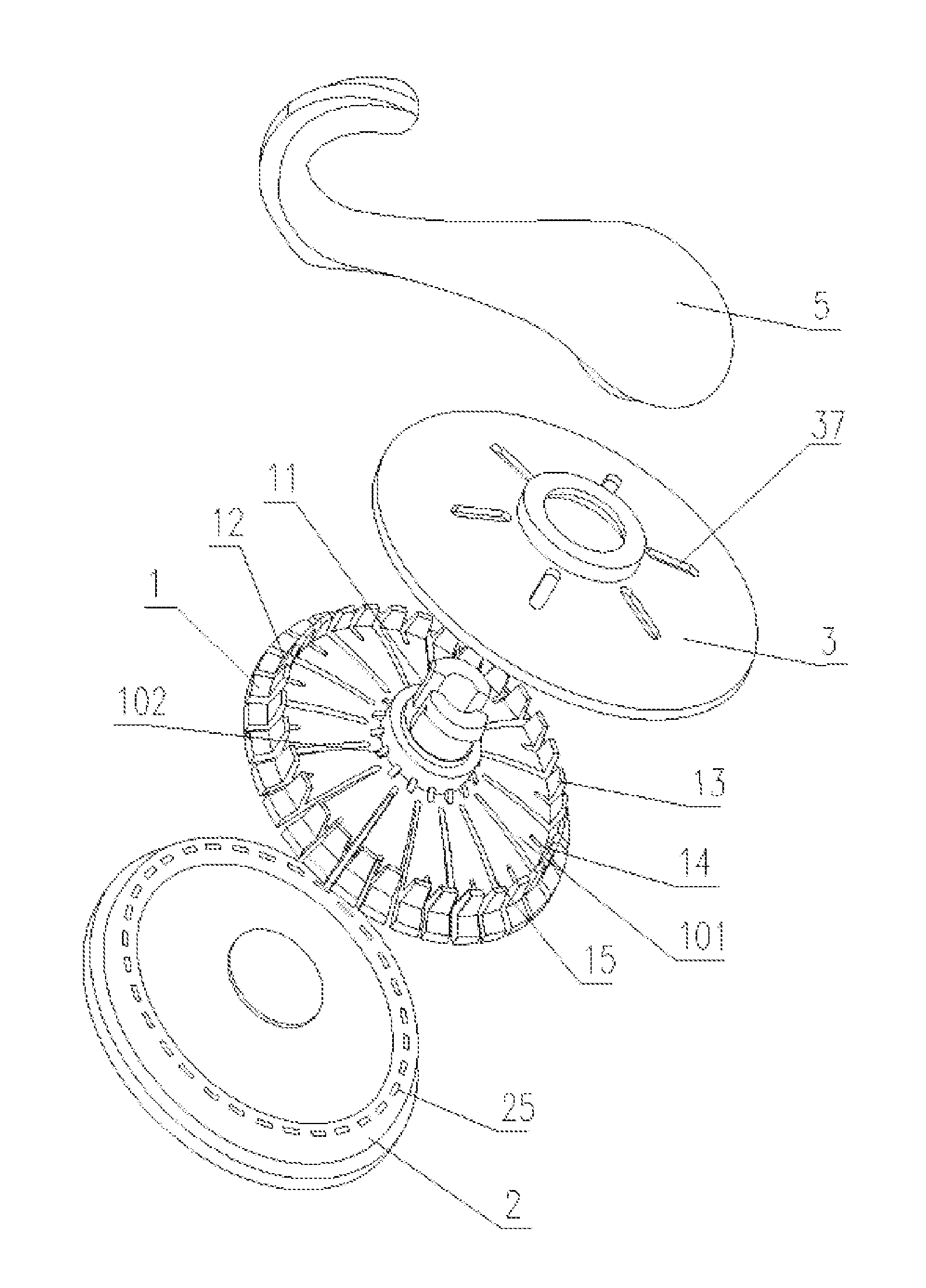
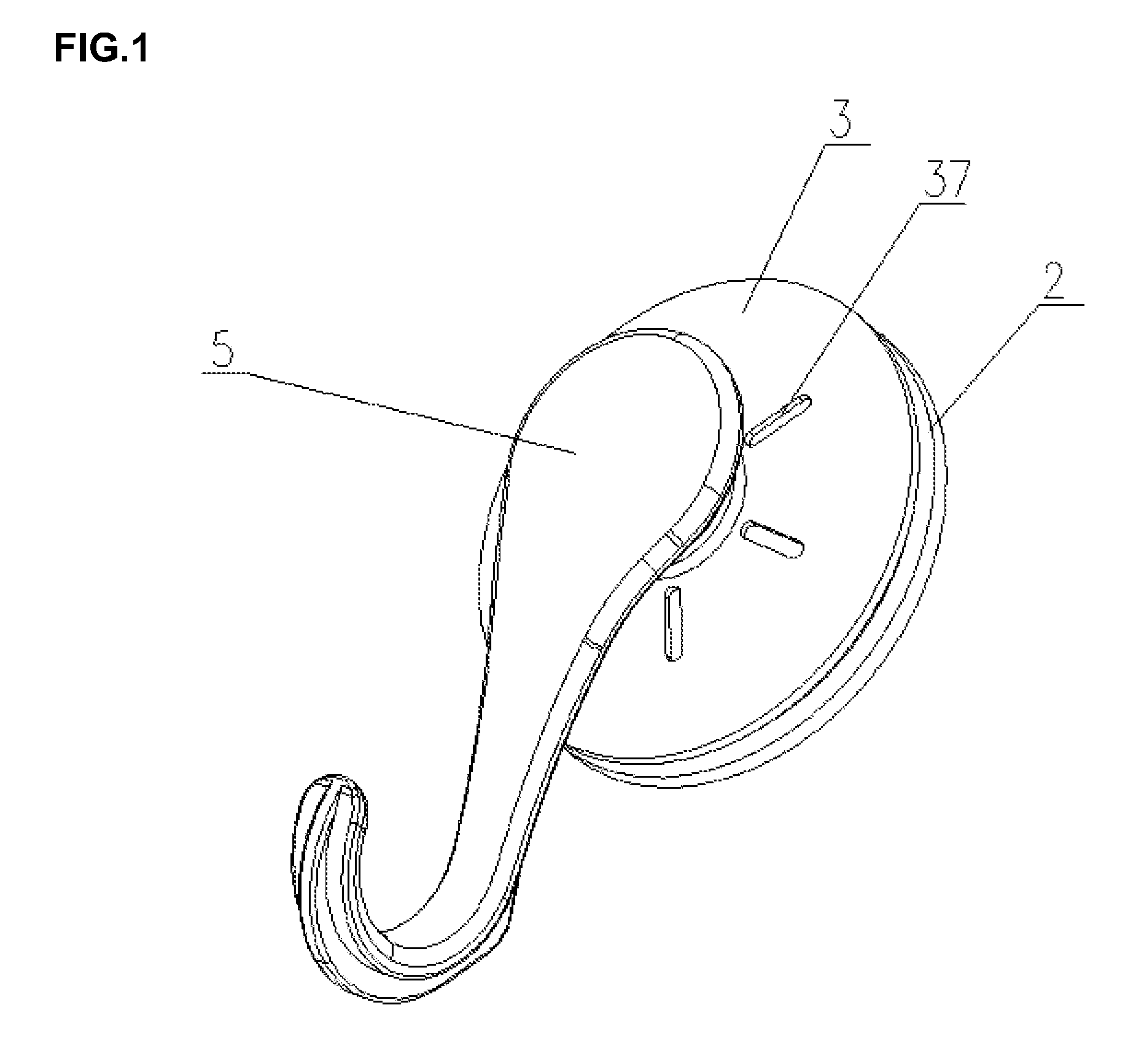
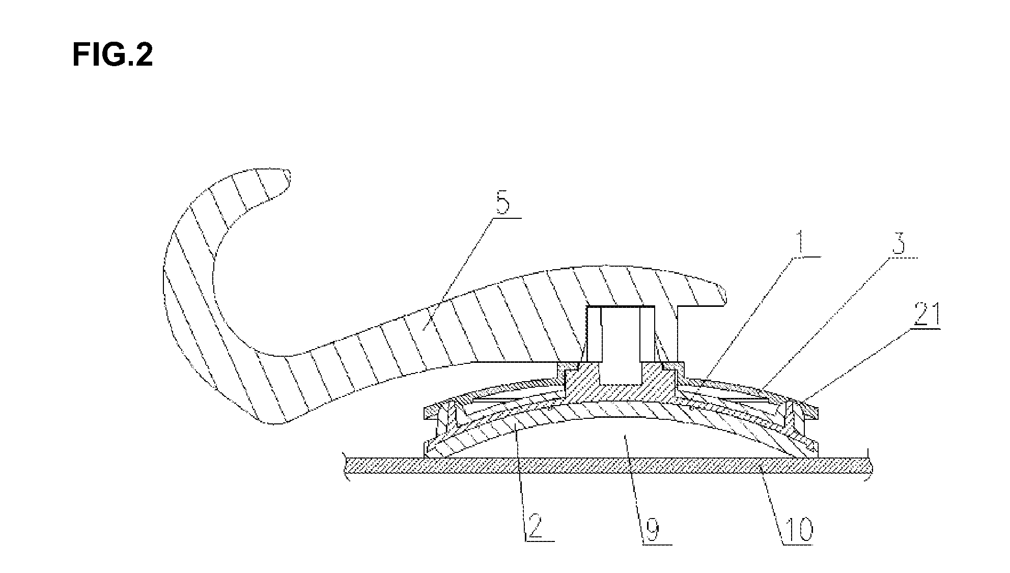
[0054]As shown in FIG. 1-FIG. 3, the invention discloses a type of suction cup with a bowl-shaped framework, comprising bowl-shaped framework 1 which is deformable, cup body 2 wrapping up the framework, connecting rod 11 disposed on the back surface of the framework and passing through the cup body, bowl-shaped cup cover 3 disposed on the connecting rod and covering the back surface of the cup body, and a hooking element provided on the back surface of the cup cover and connected to the connecting rod; wherein (in a preferred embodiment) the hooking element is hook 5, connected to the connecting rod via a buckle. The framework has the shape of a disk and at its circumferential edge and on the back surface, annular protruding rib 12 is provided with an optimum height about 2-4 mm. Corresponding to the position of the annular protruding rib, through holes 25 are provided on the back surface of the cup body, which allow extending of the annular protruding rib to pass through and expose...

embodiment 2

[0060]As shown in FIG. 4, the difference between this embodiment and embodiment 1 is described below: On the adsorption surface of cup body 2, installation grooves are provided for accommodating the seals, which extend out of the opening of the grooves to form a contact friction surface 30 between the seals and the edge of the cup body. In the embodiment, sealing gaskets 16 made of a PU material are used as seals. The cup body 2 and the sealing gaskets are integrally made. The bonding affinity of sealing gaskets 16 is higher than that of cup body 2, so that the gaskets are more easily attached to the supporting surface, enhancing the sealing effect. In addition, the bonding between the sealing gaskets and the cup body is good, and they are not prone to separation.

embodiment 3

[0061]As shown in FIG. 5, the difference between this embodiment and embodiment 2 is described below: Two seal rings 17 and 18 of different diameters are used as the seals. The installation grooves are two annular grooves corresponding to the two seal rings, enclosing the center of the adsorption surface of cup body 2. The larger seal ring 18 and the edge of cup body 2 form a contact friction surface 30.


PUM


Abstract

A suction cup, including a bowl-shaped framework, a cup body covering the framework, a connecting rod on a back surface of the framework and passing through the cup body, a bowl-shaped cup cover placed on the connection rod and covering the back surface of the cup body, and an annular protruding rib placed on the periphery of the back surface of the framework, which is in direct contact with the inner surface of the cup cover for effectively transfer the pressing force to make the suction cup less likely to fall off from the supporting surface.

Description

FIELD OF THE INVENTION[0001]This invention relates to a type of suction cup for civilian use, in particular a type of suction cup with bowl-shaped framework.BACKGROUND OF THE INVENTION[0002]Suction cups for civilian use are mainly for people to hang articles on a supporting surface such as walls. As it can be relocated to any positions at will, it can be conveniently used to hang towels, clothing articles, etc. Such suction cup is easy to use and can maintain attachment via vacuum assisted by adhesion, without drilling on the wall, it has therefore been widely used.[0003]Existing suction cups may be made with or without a framework. Traditional suction cup without a framework is normally made of soft plastic integrally formed by injection molding. However, such suction cup cannot fully discharge air between the cup's adsorption surface and the supporting surface, and air may easily seep in via the edge of the adsorption surface, the adsorptive force is thus reduced and insufficient....

Claims


Application Information

Patent Timeline
Patent Type & Authority Applications(United States)
IPC IPC(8): F16B47/00F16M13/02
CPCF16B47/006F16M13/022F16B47/00A47K10/14A47K2201/02
Inventor SHI, ZHENGBING
Owner ZHONGSHAN TAILI HOUSEHOLD PROD MFG
Why Eureka
Try Eureka