Planar Transformer

Active Publication Date: 2015-11-19
PHOENIX CONTACT GMBH & CO KG
View PDF6 Cites 8 Cited by
  • Summary
  • Abstract
  • Description
  • Claims
  • Application Information

AI Technical Summary

Benefits of technology

[0014]By providing the magnetic core rings in form of two-part yoke cores and the windings including the coupling winding as integral parts of the plate-shaped conductor substrate, manufacturing of the planar transformer is simplified, since it is only necessary to insert the legs of the yoke cores

Problems solved by technology

Because the winding has to be wound around the ferromagnetic cores, manufact

Method used


Image

  • Planar Transformer
  • Planar Transformer
  • Planar Transformer

Examples


Embodiment Construction

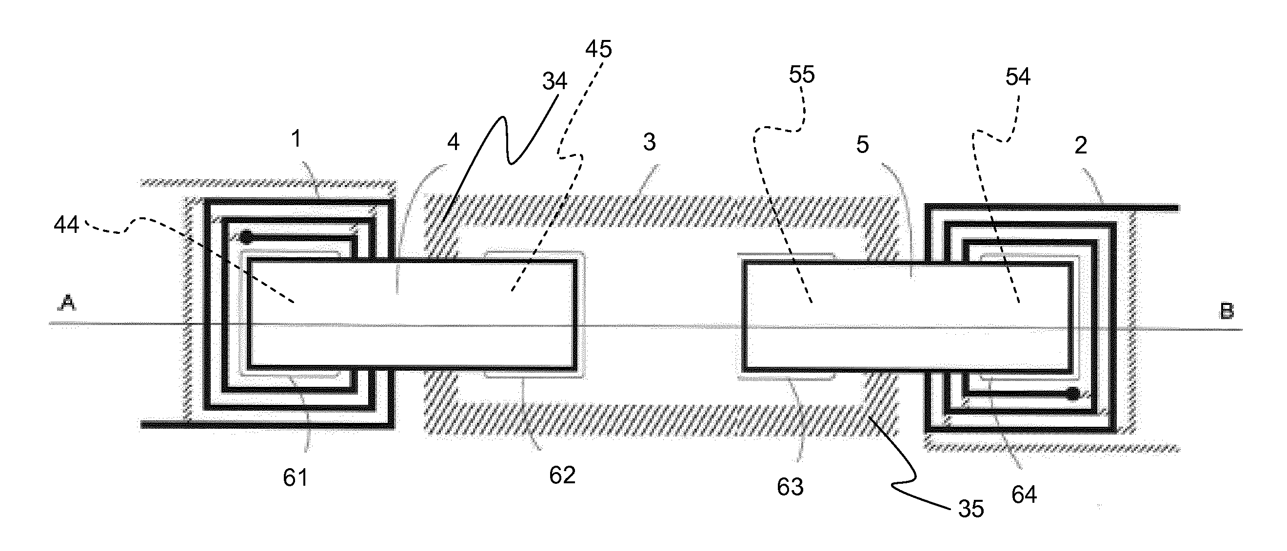
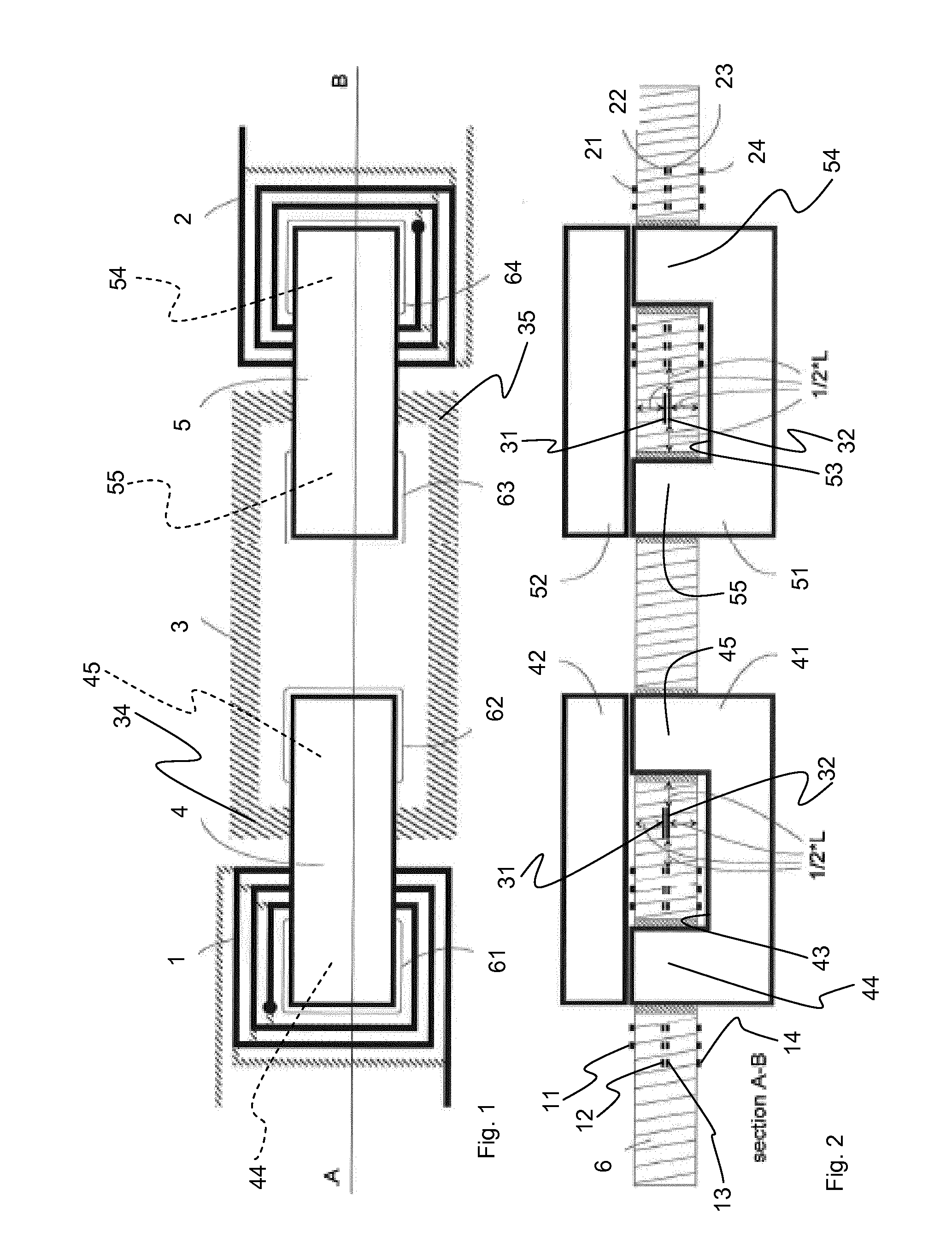
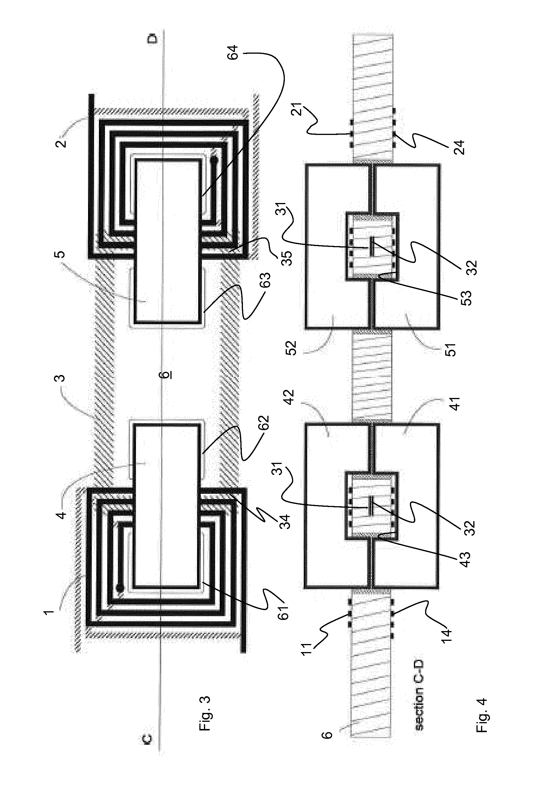
[0030]FIGS. 1 and 2 illustrate a first embodiment of a planar type transformer according to the invention. Principal parts of the transformer include a primary winding 1, a secondary winding 2, a coupling winding 3, a first two-part magnetic core ring 4, a second two-part magnetic core ring 5, and a single plate-shaped conductor substrate 6. Magnetic core rings 4, 5 each comprise two yoke core halves 41, 51, and 42, 52, which can be closed to form a ring 4 with a first ring core opening 43 and a ring 5 with a second ring core opening 53. Magnetic core rings 4, 5 each have passing legs 44, 45 and 54, 55 and connecting legs between the passing legs. Leg 44 and 54, respectively, may belong to the one or to the other core half 41, 42 and 51, 52, respectively, or may even be divided, as illustrated in FIG. 9. Plate-shaped conductor substrate 6 has two pairs of recesses 61, 62, and 63, 64 which define openings for the passing legs 44, 45 and 54, 55 of magnetic core rings 4, 5. Recess pair...


PUM


Abstract

A planar transformer is provided, which comprises a plate-shaped conductor substrate with integrated primary winding, secondary winding and coupling winding. The conductor substrate has pairs of recesses, and a respective two-part ferromagnetic core having yoke legs is inserted through each pair of recesses. One leg of each core is surrounded by the primary winding or the secondary winding, while the coupling winding is looped around the remaining legs of the cores. At least a minimum total isolation separation distance made up of partial isolation separation distances between the coupling winding and adjacent yoke legs or adjacent windings is maintained for electrical isolation between the primary winding and the secondary winding.

Description

FIELD OF THE INVENTION[0001]The invention relates to a planar transformer comprising a primary winding, a secondary winding, a coupling winding, and a conductor substrate which carries one or more magnetic core rings.BACKGROUND OF THE INVENTION[0002]U.S. Pat. No. 8,022,802 B2 relates to a sensor for measuring electrical parameters in a high voltage environment and comprises isolation transformers in several embodiments, including one embodiment with a single main circuit board for a plurality of adjacently disposed windings which are coupled magnetically by magnetic core rings, and a further embodiment with a main circuit board, a secondary circuit board and two magnetic core rings which extend through openings of the main and secondary circuit boards. The primary winding and the secondary winding are arranged in and on the main circuit board, while the coupling winding for coupling the two magnetic core rings is arranged on the secondary circuit board. There is some intermediate sp...

Claims


Application Information

Patent Timeline
IPC IPC(8): H01F27/28H01F27/24
CPCH01F27/2804H01F2027/2809H01F27/2895H01F27/24H01F2027/2819
Inventor BLANKE, JOERG
Owner PHOENIX CONTACT GMBH & CO KG
Why Eureka
Try Eureka