Gear support structure

a gear train and support structure technology, applied in the direction of camera filters, camera focusing arrangement, printers, etc., can solve the problems of increasing the size of the gear mechanism, unsuitable for an apparatus, gears of the gear train are susceptible to rattling and noise, etc., and achieve excellent space-utilization efficiency, compact size, and high degree of precision

Inactive Publication Date: 2009-05-14
HOYA CORP
View PDF12 Cites 5 Cited by
  • Summary
  • Abstract
  • Description
  • Claims
  • Application Information

AI Technical Summary

Benefits of technology

[0006]The present invention has been devised in view of the above described drawbacks and provides a gear support structure which is compact in size, excellent in space-utilization efficiency and capable of holding the intermediate gear with a high degree of precision.
[0021]According to the present invention, each gear and the spring member can be arranged in a space-saving manner because the resilient support legs of the spring member sit at positions that do not interfere with either the two gears (driving and driven gears) which mesh with the intermediate gear or the gear shafts of the two gears. Additionally, since the lengths of the resilient support legs of the spring member are not limited by the configuration of the two gears, and also since the size and the degree of biasing force of the spring member can be freely determined by freely selecting the lengths of the resilient support legs, the intermediate gear can be supported with stability at a high degree of precision by suppressing any variations in the biasing force due to dimensional errors in the manufactured spring members. Additionally, as compared with the method of reducing variations in biasing force between the manufactured spring members by severely controlling the accuracy of small-sized spring members produced, a reduction in the production cost of the spring member is achieved if the present invention is applied to the gear support mechanism.

Problems solved by technology

The former drive mechanism tends to be long in the axial direction of the rotary output shaft and thus unsuitable for an apparatus which needs to be slimmed down in the axial direction.
For instance, in an AF (autofocus) mechanism for an imaging device such as a digital camera, gears of the gear train are susceptible to rattling and produce noise if the support for the intermediate gear has excessive play because the motor is driven intermittently at high speed.
If the spring washer with this kind of shape is increased in size, the distances between the gear shafts of the intermediate gear and the associated gears in front and in the rear of the intermediate gear need to be increased to prevent these gears from interfering with the spring washer, which becomes a cause of increasing the size of the gear mechanism.

Method used


Image

  • Gear support structure
  • Gear support structure
  • Gear support structure

Examples


Embodiment Construction

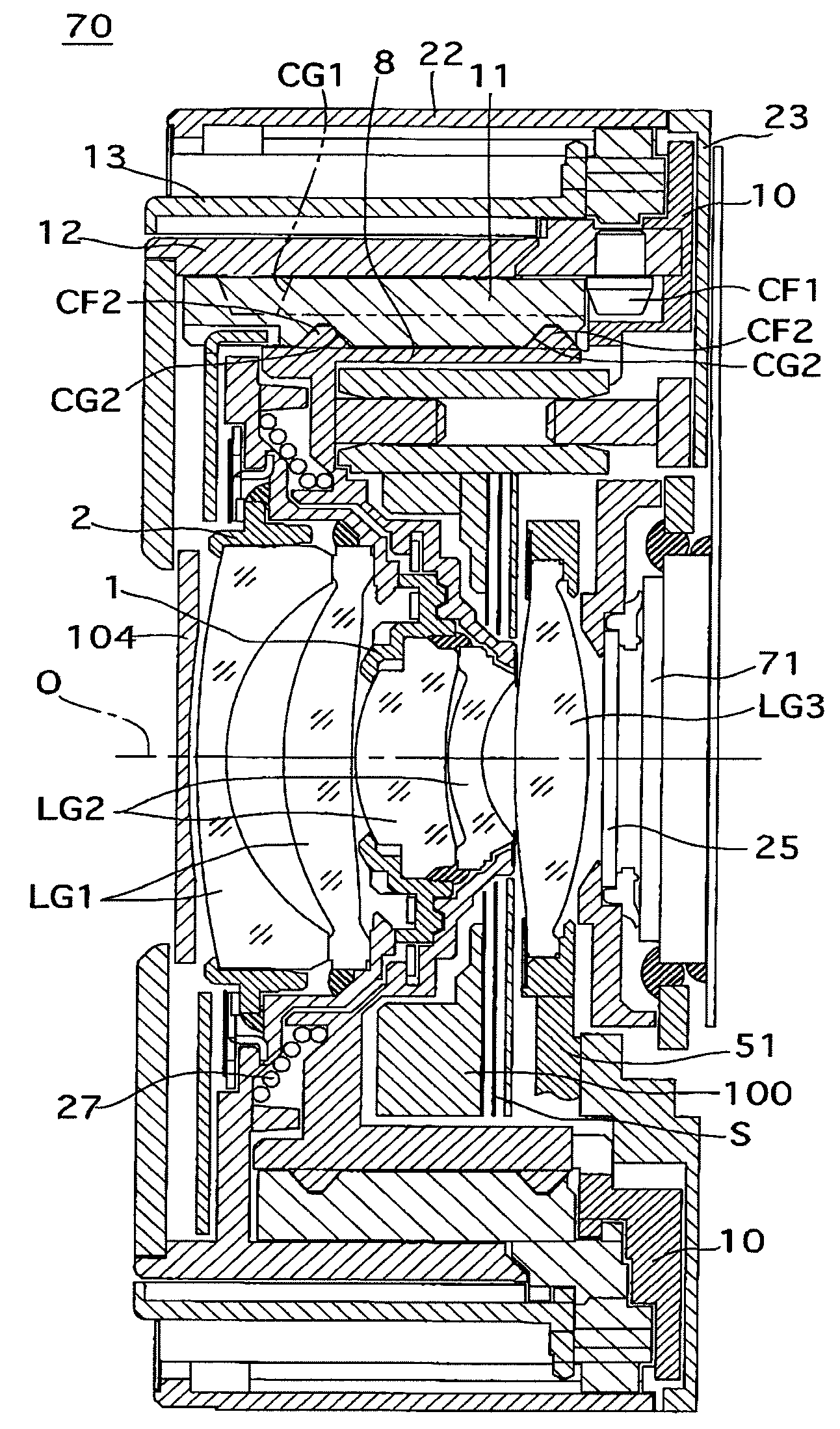
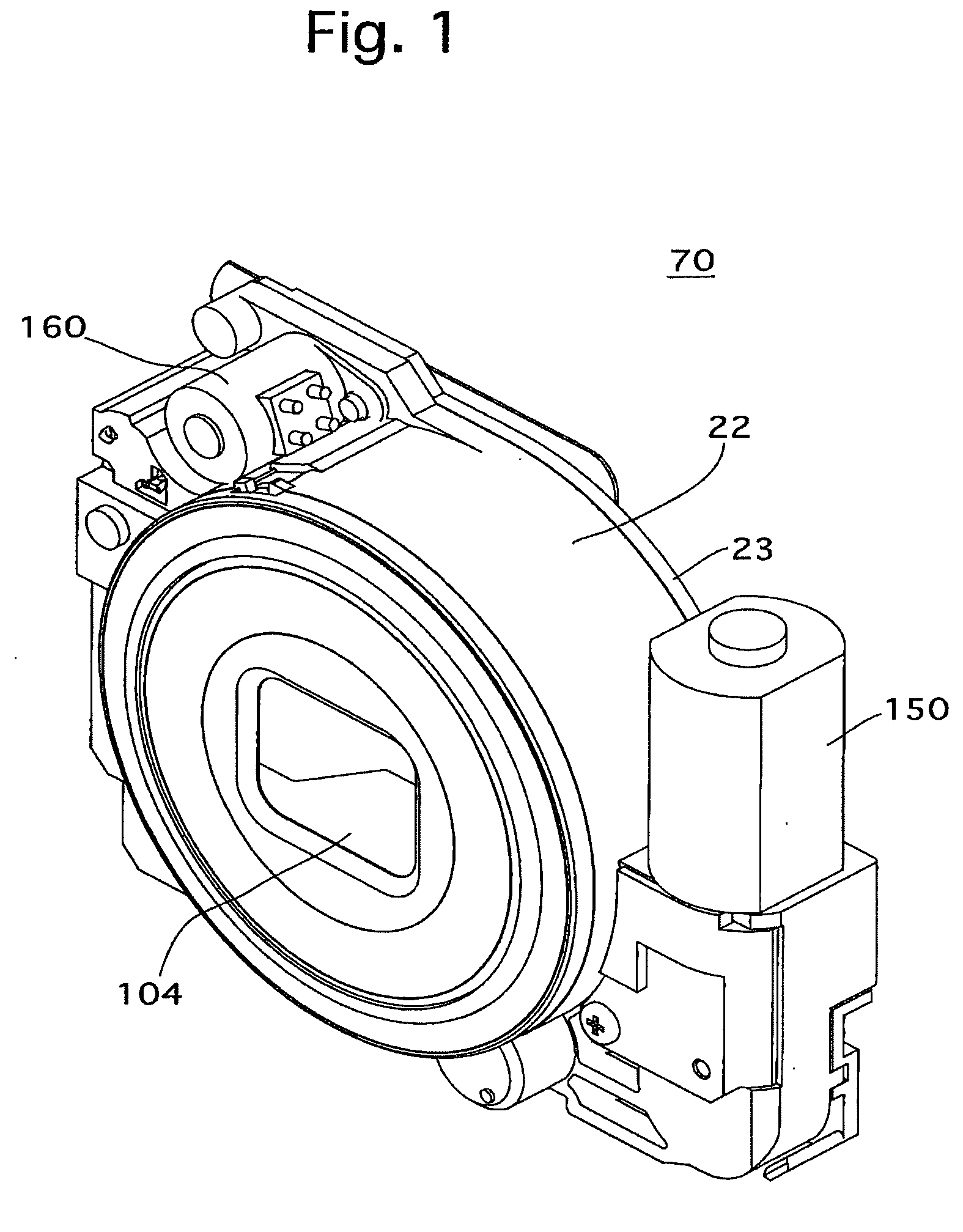
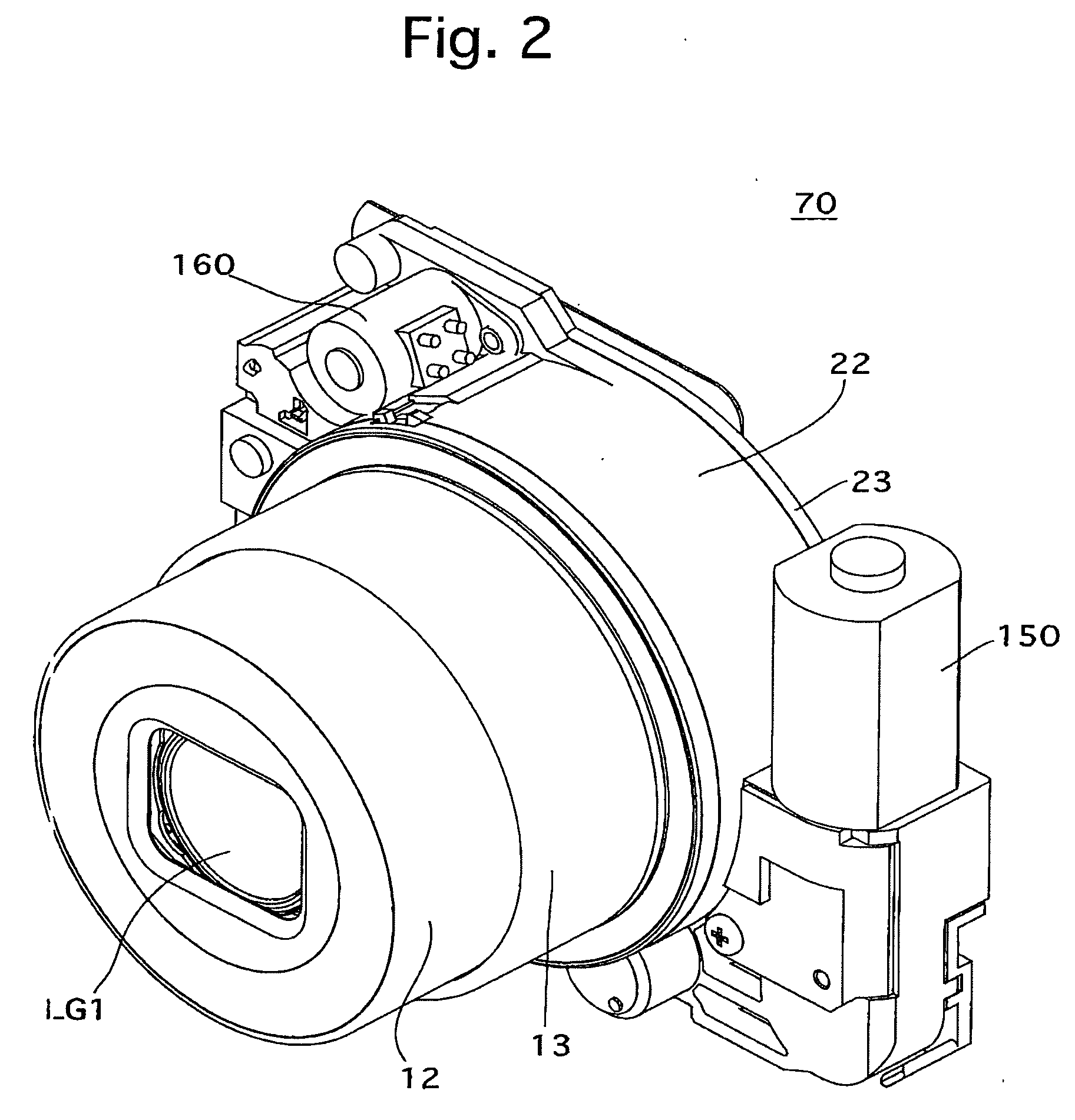
[0040]The brief description of the structure of a zoom lens barrel 70 including a gear support structure according to the present invention will be hereinafter discussed with reference to FIGS. 1 through 4. A photographing optical system of the zoom lens barrel 70 is provided with a first lens group LG1, a second lens group LG2, a set of shutter blades S that also serves as a set of diaphragm blades, a third lens group (AF lens group) LG3, a low-pass filter (optical filter) 25 and an image pickup device (image sensor) 71, in that order from the object side. In the following descriptions, the optical axis direction refers to a direction along or parallel to the photographing optical axis O of this photographing optical system.

[0041]The low-pass filter 25 and the image pickup device 71 are integrated as a single unit and this unit is fixed to an image pickup device holder 23, and the image pickup device holder 23 is fixed to the back of a housing 22 of the zoom lens barrel 70. A zoom ...


PUM


Abstract

A gear support mechanism for supporting two gears and an intermediate gear which meshes with the two gears to transfer rotation of one of the two gears to the other, includes a gear-shaft support member(s) which supports a gear shaft of the intermediate gear; and a spring member installed between the gear-shaft support member and the intermediate gear. The spring member includes a gear contacting portion which is in contact with the intermediate gear, and resilient support legs extend radially from the gear contacting portion and are in contact with the gear-shaft support member, the spring member biasing the intermediate gear in a direction of an axis of the gear shaft. Each of the two gears is positioned in an inter-leg space between adjacent resilient support legs as viewed in a direction along the axis of the gear shaft.

Description

BACKGROUND OF THE INVENTION[0001]1. Field of the Invention[0002]The present invention relates to a support structure for supporting gears of a gear train for power transmission.[0003]2. Description of the Related Art[0004]In drive mechanisms for moving an object to be driven by translating rotary motion of a rotary output shaft of a drive source such as a motor into axial (linear) motion, two types of drive mechanisms are known in the art: a drive mechanism which directly connects a lead screw (leadscrew) to the rotary output shaft, and a drive mechanism which transfers rotational torque from the rotary output shaft to another lead screw via a gear train. The former drive mechanism tends to be long in the axial direction of the rotary output shaft and thus unsuitable for an apparatus which needs to be slimmed down in the axial direction. In the latter type of drive mechanism that uses a gear train, the drive mechanism can be slimmed down in the axial direction because a drive source...

Claims


Application Information

Patent Timeline
Patent Type & Authority Applications(United States)
IPC IPC(8): F16H57/02
CPCF16H57/0006F16H57/021F16H2057/0221G02B7/102Y10T74/19619G03B11/04G03B17/04G03B17/12Y10T74/19633G03B3/10G03B11/043
Inventor NOMURA, HIROSHIHAGIHARA, KOJI
Owner HOYA CORP
Why Eureka
Try Eureka