Lighting Control System

a control system and light technology, applied in the field of light control system, to achieve the effect of reducing power consumption, less power, and reducing the power demand of the first sensor devi

Inactive Publication Date: 2015-11-19
C P ELECTRONICS
View PDF1 Cites 9 Cited by
  • Summary
  • Abstract
  • Description
  • Claims
  • Application Information

AI Technical Summary

Benefits of technology

[0007]In this way the invention can help to reduce power consumption by deactivating the light when the room is not occupied. In addition, since the first sensor device is not always transmitting, it uses less power than a conventional system which sends out a continuous stream of updates as to the occupancy of a room. Therefore the power demands of the first sensor device are lower, and it can be installed more easily, without the need for a dedicated power supply, or as powerful a supply.
[0032]It may be that the first sensor device comprises a battery. This can be advantageous since a battery powered sensor can be installed anywhere, without the difficulty of having to arrange a power supply. The battery may be rechargeable.

Problems solved by technology

In addition, since the first sensor device is not always transmitting, it uses less power than a conventional system which sends out a continuous stream of updates as to the occupancy of a room.

Method used


Image

  • Lighting Control System
  • Lighting Control System
  • Lighting Control System

Examples


Embodiment Construction

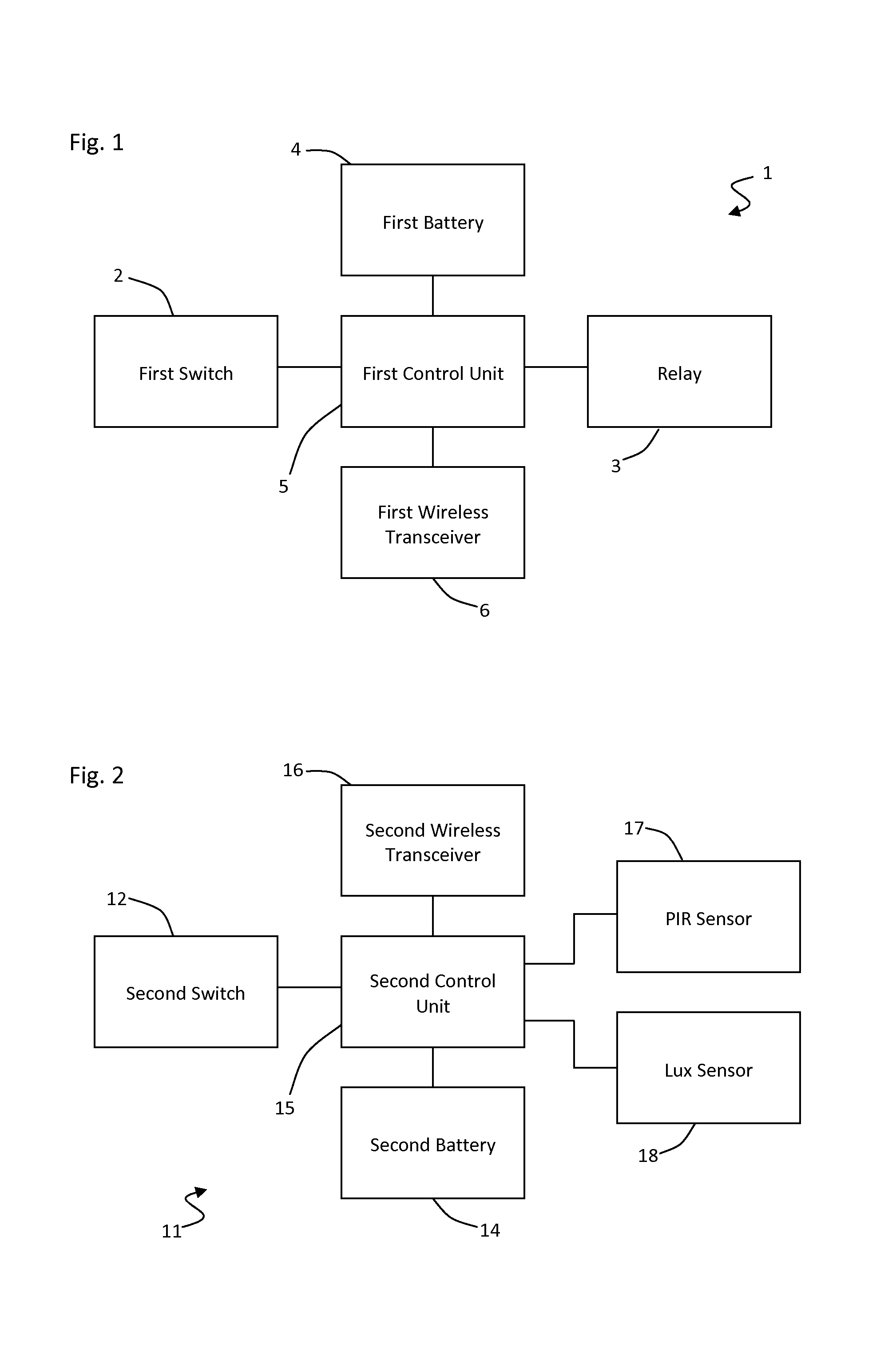
[0041]FIG. 1 shows a lighting controller 1 according to the invention. The lighting controller 1 is suitable for use in place of an existing wall mounted light switch, and comprises a user operable switch 2 on the front of the device and an internal relay device 3. The relay device 3 is used to control the supply of power to at least one light, therefore the relay device 3 can be used to make a connection and so turn the lights on, or break the connection to turn the lights off.

[0042]The lighting controller 1 further comprises a first battery 4 and a first control unit 5. The first control unit 5 draws power from the first battery 4 to operate. The first battery 4 is a rechargeable battery which derives its charge current through the lighting load on the relay device 3. As such, when the first battery 4 is depleted through use, the first control unit 5 can cause the first battery 4 to recharge automatically, without the need for the first battery 4 to be removed or replaced. However...


PUM


Abstract

A method for controlling a light, comprising: providing a first sensor device (11) comprising a first transmitter and a first occupancy sensor; providing a lighting controller (1) comprising a receiver and a second sensor; and transmitting an occupancy signal from the first transmitter to the receiver. The occupancy signal comprises a repeated cycle of transmission phases and silent phases, such that during a transmission phase the transmitter transmits and during a silent phase the transmitter does not transmit. The method further comprises activating the light when the second sensor is triggered; and deactivating the light after a period of time, the length of the period being determined at least in part by the occupancy signal transmitted by the first transmitter.

Description

BACKGROUND[0001]For both environmental and cost reasons, it is important to reduce energy use wherever possible. One major source of wasted energy is lighting, with many electrical lights often being left on unnecessarily. Occupancy detectors are widely used to turn lights on and off automatically when a person enters and leaves a room, and so conserve energy by ensuring that an unoccupied room is not unnecessarily illuminated.[0002]Typically, occupancy detectors work by detecting whether a person is in an area using PIR, microwave or ultrasonic sensors. They can be found in two basic forms: a presence detector, which turns lights on automatically when an occupant is detected, and then turns the lights off after an area is vacated; or an absence detector which requires a manual switch to turn lights on, but similarly turns lights off automatically after an area is vacated.[0003]Normally occupancy detectors are either wall mounted or ceiling mounted. In a typical retrofit application...

Claims


Application Information

Patent Timeline
Patent Type & Authority Applications(United States)
IPC IPC(8): H05B37/02
CPCH05B37/0272H05B37/0227H05B39/088H05B47/11H05B47/13H05B47/19Y02B20/40
Inventor MANS, PAULMILNER, MERLIN
Owner C P ELECTRONICS
Why Eureka
Try Eureka