Systems and methods for reducing an overpressure caused by a vapor cloud explosion

Active Publication Date: 2015-11-26
EXXON RES & ENG CO
View PDF4 Cites 2 Cited by
  • Summary
  • Abstract
  • Description
  • Claims
  • Application Information

AI Technical Summary

Benefits of technology

[0006]Systems and methods for reducing an overpressure caused by an explosion of a vapor cloud are provided. In one or more embodiments, the system can include one or more sensors operable to detect the explosion of the vapor cloud. The system can also include one or more igniters operable to ignite the vapor cloud at multiple locations throughout, after the explosion of the vapor cloud is detected, to provide a discrete combustion zone at each location. Each combustion zone can form a discrete pressure wave, thereby reducing the ove

Problems solved by technology

A potential danger with hydrocarbon and other chemical extraction or production, processing, refining, and/or storage facilities is that vapors, e.g., gaseous hydrocarbons or other combustible vapors, can escape into the atmosphere and form a vapor cloud.
As the flame front expands, it can accelerate toward sonic velocity and cause the formation of an overpressure as it passes around structures in its way, such as piping, process equipment, and buildings.
This overpressure can have a significant and detrimental effect on the structures, as well as the p

Method used


Image

  • Systems and methods for reducing an overpressure caused by a vapor cloud explosion
  • Systems and methods for reducing an overpressure caused by a vapor cloud explosion
  • Systems and methods for reducing an overpressure caused by a vapor cloud explosion

Examples


examples

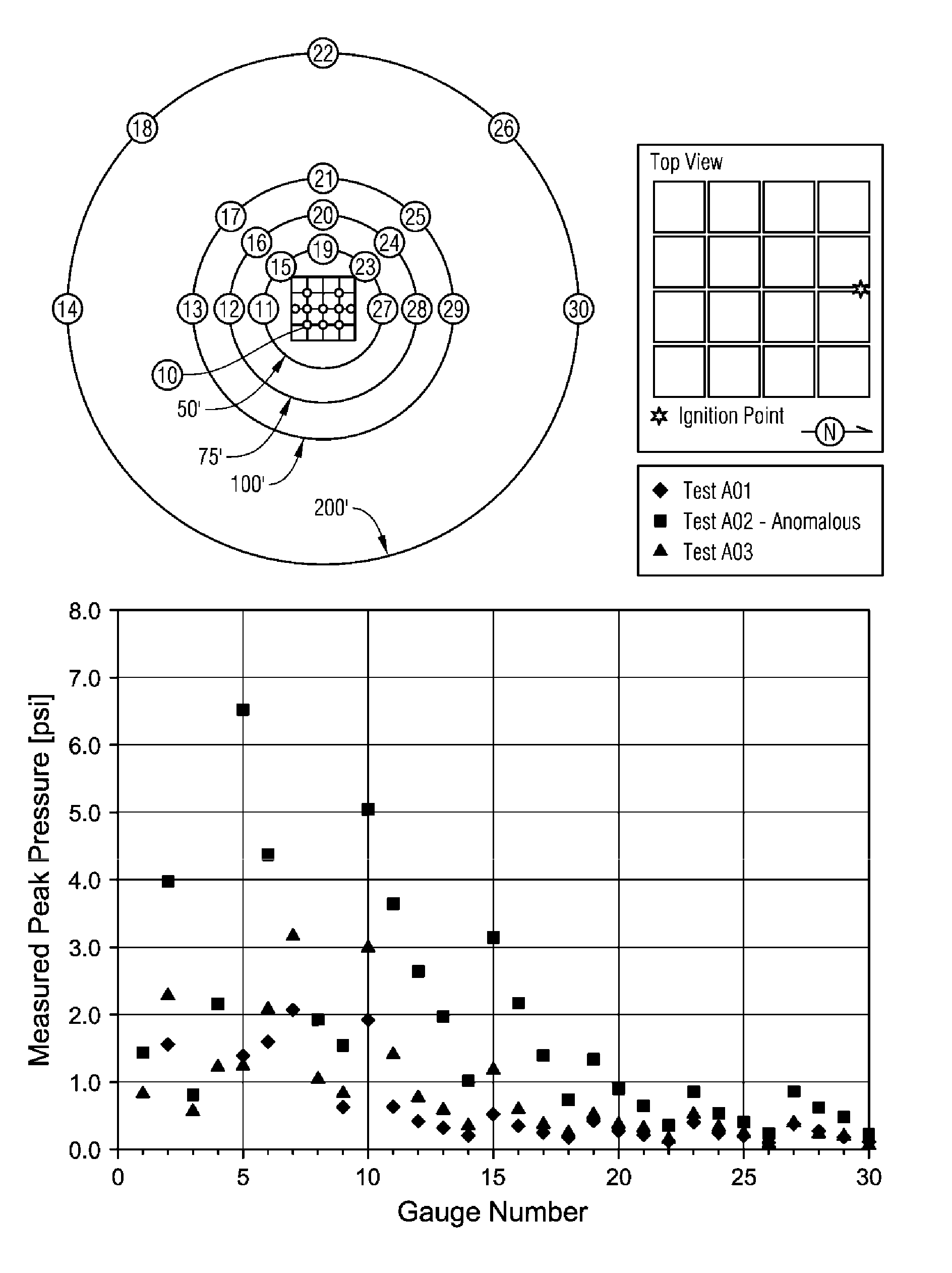
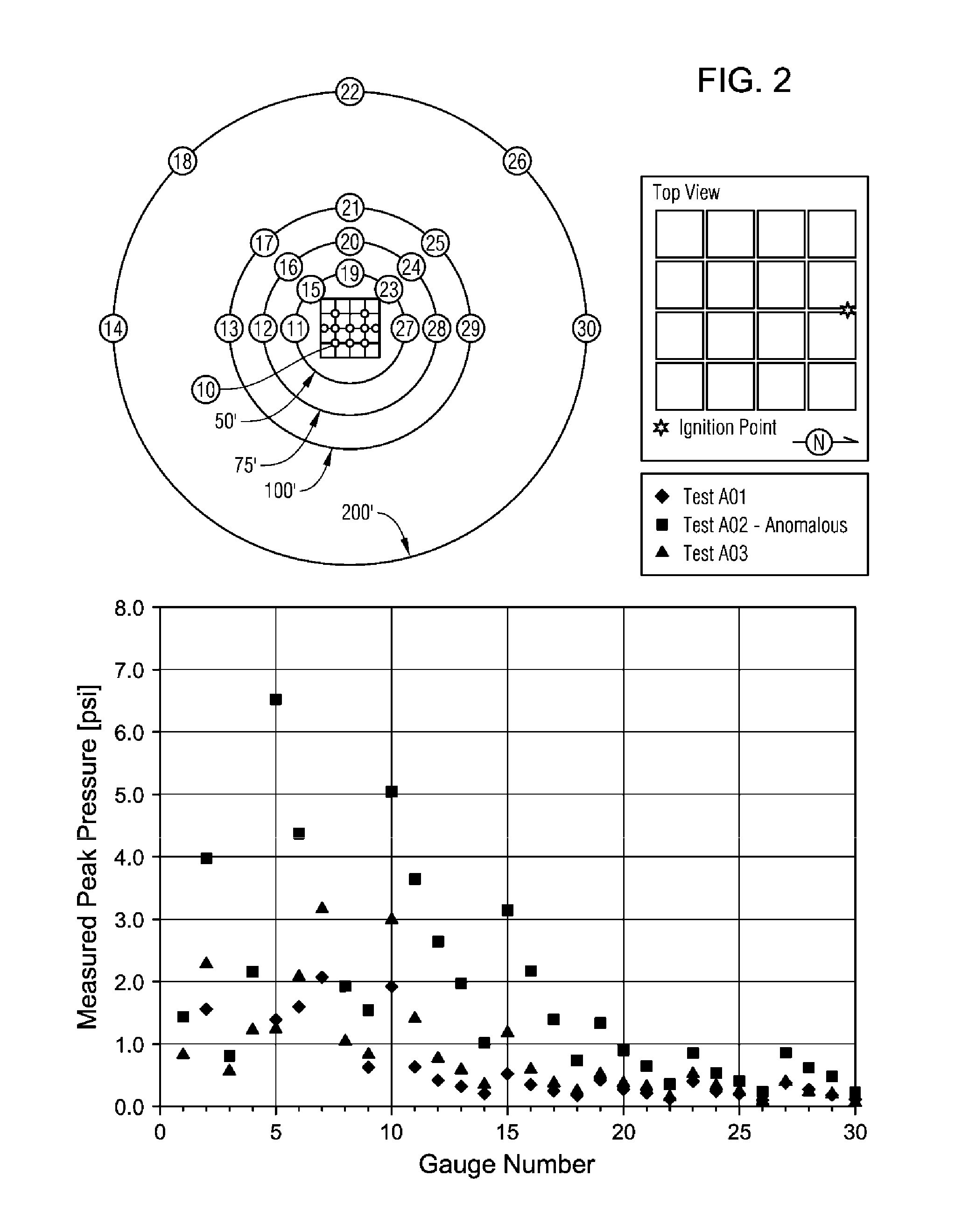
[0053]A series of vapor cloud explosion (VCE) tests were conducted utilizing multiple simultaneous ignition sources using near stoichiometric homogenous propane-air mixtures. Table 1 summarizes the test matrix employed.

TABLE 1Test MatrixMaximumTest NumberFlameConges-RigTestof IgnitionTraveltionFlameDimen-SeriesLocationsDistance (ft)LevelExpansionsionsZ011-Center17Medium3D24 ft ×A1-Edge2724 ft ×B2-Edge176 ft C4-Edge127.3 m ×D5-(4 edge + 127.3 m ×1 center)1.8 m  E5-Interior8.5F2-Corner24

[0054]The “maximum flame travel distance” is the longest distance a flame can travel between an ignition source before encountering the flame front from another ignition source (assuming equal flame speeds) or the edge of the test rig, whichever is greater. The maximum flame travel distances for each test series are given in Table 1.

[0055]The test rig was employed a 4×4 cube configuration (24 ft×24 ft×6 ft), with a medium level of congestion and 3D flame expansion (i.e., open roof and sides). A medium ...

embodiment a

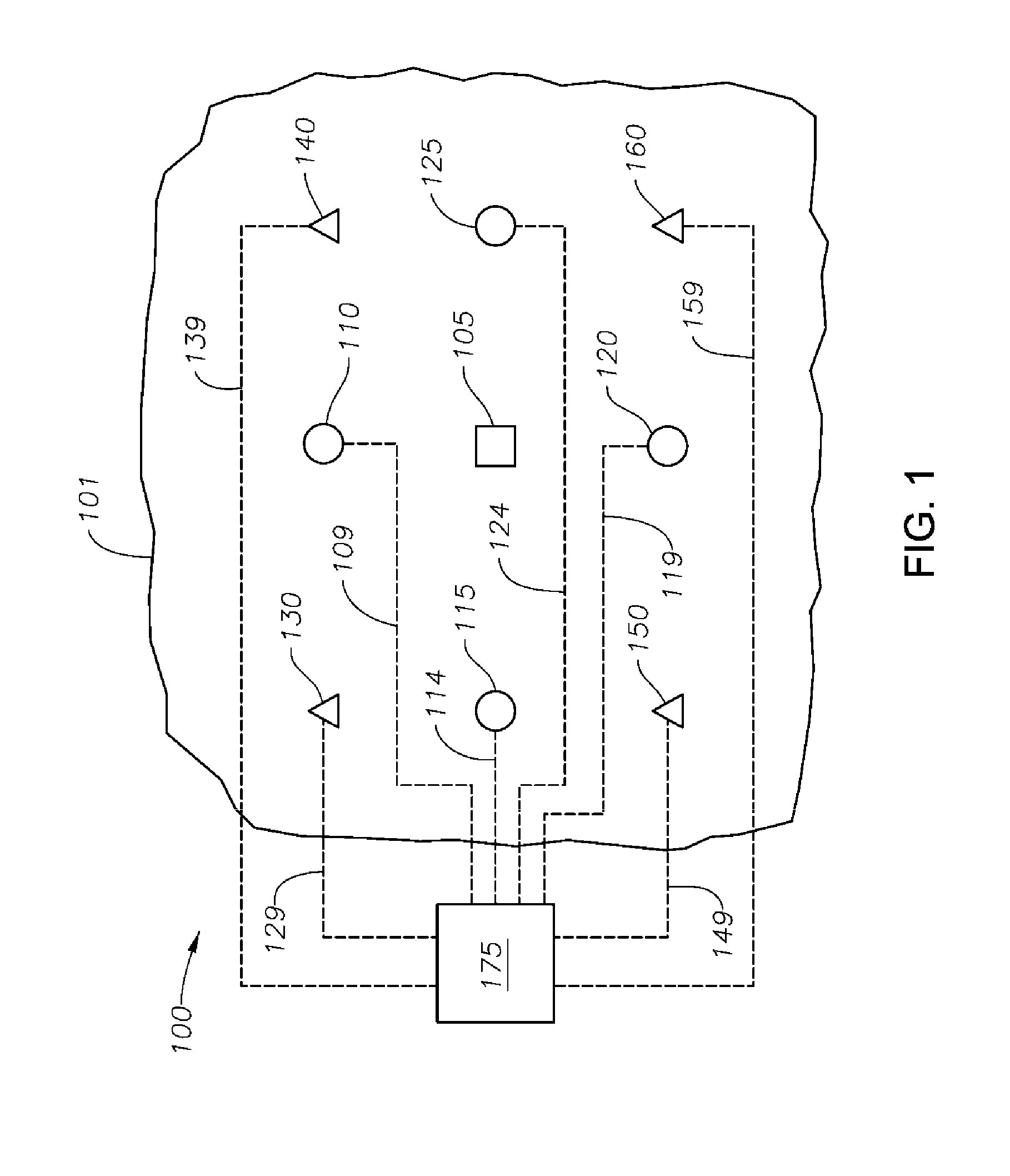
[0070]A system for reducing overpressure caused by an explosion of a vapor cloud comprising: one or more sensors operable to detect the explosion of the vapor cloud; and one or more igniters operable to ignite the vapor cloud at one or more locations after the explosion of the vapor cloud is detected, wherein each of the one or more igniters provides a discrete combustion zone, and each combustion zone forms a discrete pressure wave, thereby reducing overpressure caused by the explosion of the vapor cloud.

embodiment b

[0071]The system according to Embodiment A, the system comprising a plurality of igniters operable to ignite the vapor cloud at multiple locations.


PUM


Abstract

Systems and methods for reducing an overpressure caused by an explosion of a vapor cloud are provided. In one or more embodiments, the system can include one or more sensors operable to detect the explosion of the vapor cloud. The system can also include one or more igniters operable to ignite the vapor cloud at locations throughout, after the explosion of the vapor cloud is detected, to provide a discrete combustion zone at each location. Each combustion zone can form a discrete pressure wave, thereby reducing the overpressure caused by the explosion of the vapor cloud.

Description

PRIORITY CLAIM[0001]This application claims the benefit of and priority to U.S. Ser. No. 61 / 635,942, filed Apr. 20, 2012.FIELD[0002]Embodiments described herein generally relate to systems and methods for reducing an overpressure development caused by a vapor cloud explosion. More particularly, such embodiments relate to systems and methods for reducing an overpressure caused by a vapor cloud explosion by reducing a distance a given pressure wave front or flame front travels.BACKGROUND[0003]A potential danger with hydrocarbon and other chemical extraction or production, processing, refining, and / or storage facilities is that vapors, e.g., gaseous hydrocarbons or other combustible vapors, can escape into the atmosphere and form a vapor cloud. Being combustible, such vapor cloud can be unintentionally ignited causing an explosion or what is commonly referred to as a “vapor cloud explosion” or simply “VCE.” During a vapor cloud explosion, a flame front forms and outwardly expands from ...

Claims


Application Information

Patent Timeline
IPC IPC(8): A62C3/02A62C99/00A62C3/06
CPCA62C3/0285A62C99/00A62C3/06A62C99/0054
Inventor BARON, NORBERT
Owner EXXON RES & ENG CO
Why Eureka
Try Eureka