Pressure shut-off valve for high-pressure cleaner and high-pressure cleaner having pressure shut-off valve

A cut-off valve and cleaner technology, applied in the field of pressure cut-off valves, can solve problems such as unreliable switching and high manufacturing costs, and achieve the effects of improving flow resistance, reducing manufacturing costs, and reducing flow resistance

Pending Publication Date: 2022-05-13
ANDREAS STIHL AG & CO KG
View PDF0 Cites 0 Cited by
  • Summary
  • Abstract
  • Description
  • Claims
  • Application Information

AI Technical Summary

Problems solved by technology

[0003] The disadvantage of such pressure shut-off valves is that they d

Method used


Image

  • Pressure shut-off valve for high-pressure cleaner and high-pressure cleaner having pressure shut-off valve
  • Pressure shut-off valve for high-pressure cleaner and high-pressure cleaner having pressure shut-off valve
  • Pressure shut-off valve for high-pressure cleaner and high-pressure cleaner having pressure shut-off valve

Examples


Embodiment Construction

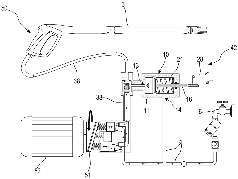
[0034] figure 1 Shown is a schematic illustration of a design of a high-pressure cleaner 1 according to the invention. The high-pressure cleaner 1 comprises a housing 2 which encloses the various system components of a hydraulic unit 50 ( Figure 3~5 ) and protect it, for example, from jets of water. A low-pressure connection 4 is provided on the housing 2, through which the suction line 5 of the high-pressure cleaner 1 ( Figure 3~5 ) with an external liquid connection 6 ( Figure 3~5 ) especially water fittings can be connected. The high-pressure cleaner 1 is then supplied with cleaning liquid via the low-pressure connection 4 during its operation. The cleaning liquid is preferably water. Other liquids, such as water mixed with cleaning agents, can also be provided as cleaning liquids. A hose drum 7 is arranged on the housing 2 of the high-pressure cleaner 1 . A high-pressure hose 8 is wound around the hose drum 7 . The high-pressure hose 8 is connected with the high...


PUM


Abstract

The invention relates to a pressure shut-off valve for a high-pressure cleaner and a high-pressure cleaner with a pressure shut-off valve, in particular to a pressure shut-off valve for a high-pressure cleaner. According to the invention, the pressure shut-off valve (10) has an effective throttle gap (30) between the valve housing (11) and the valve body (16) with a total length (a) measured in the direction of the longitudinal axis (17) of the valve body (16), the effective throttle gap (30) being part of a flow connection (12) between the inlet (13) and the outlet (14). The valve body (16) has a maximum diameter (d) extending radially with respect to the longitudinal axis (17). In a first closed position (40) of the pressure shut-off valve (10), the total length (a) of the effective throttle gap (30) is at least 50% of the maximum diameter (d) of the valve body (16).

Description

technical field [0001] The invention relates to a pressure shut-off valve for a high-pressure cleaner and to a high-pressure cleaner with such a pressure shut-off valve. Background technique [0002] High-pressure cleaners are used to pressurize a cleaning liquid, in particular water, and then spray it through a spray kit, for example a spray pipe with a nozzle head, and to clean objects with a liquid jet. To generate pressure, high-pressure cleaners include a pump, which is connected at its inlet to the suction line and at its outlet to the pressure line. The pump is supplied with liquid through the suction line. The liquid is brought under pressure by the pump and is transferred from the outlet of the pump into the pressure line. If the jetting set is open, fluid is expelled from the jetting set under high pressure. If the jetting set is switched off, the pump is deactivated in order to reduce the mechanical load. For this purpose, a pressure shut-off valve is provided...

Claims


Application Information

Patent Timeline
IPC IPC(8): F16K47/08F16K27/02F16K1/38F16K25/00B08B3/02
CPCF04B43/06F16K47/08F16K27/0254F16K1/38F16K25/005B08B3/02B08B3/026F04B49/225F04B49/24F04B49/08F04B49/03F16K17/04F16K37/0041B08B3/028B08B2203/027
Inventor K·考普S·施兰德勒
Owner ANDREAS STIHL AG & CO KG
Why Eureka
Try Eureka