
Virtual attraction controller

a virtual attraction and controller technology, applied in the direction of vehicle position/course/altitude control, process and machine control, instruments, etc., can solve the problems of difficult integration and costly maintenance of traditional control systems, and achieve the effect of facilitating facilitating identification of a location

Active Publication Date: 2015-11-26
UNIVERSAL CITY STUDIOS LLC
View PDF2 Cites 28 Cited by
  • Summary
  • Abstract
  • Description
  • Claims
  • Application Information

AI Technical Summary

Benefits of technology

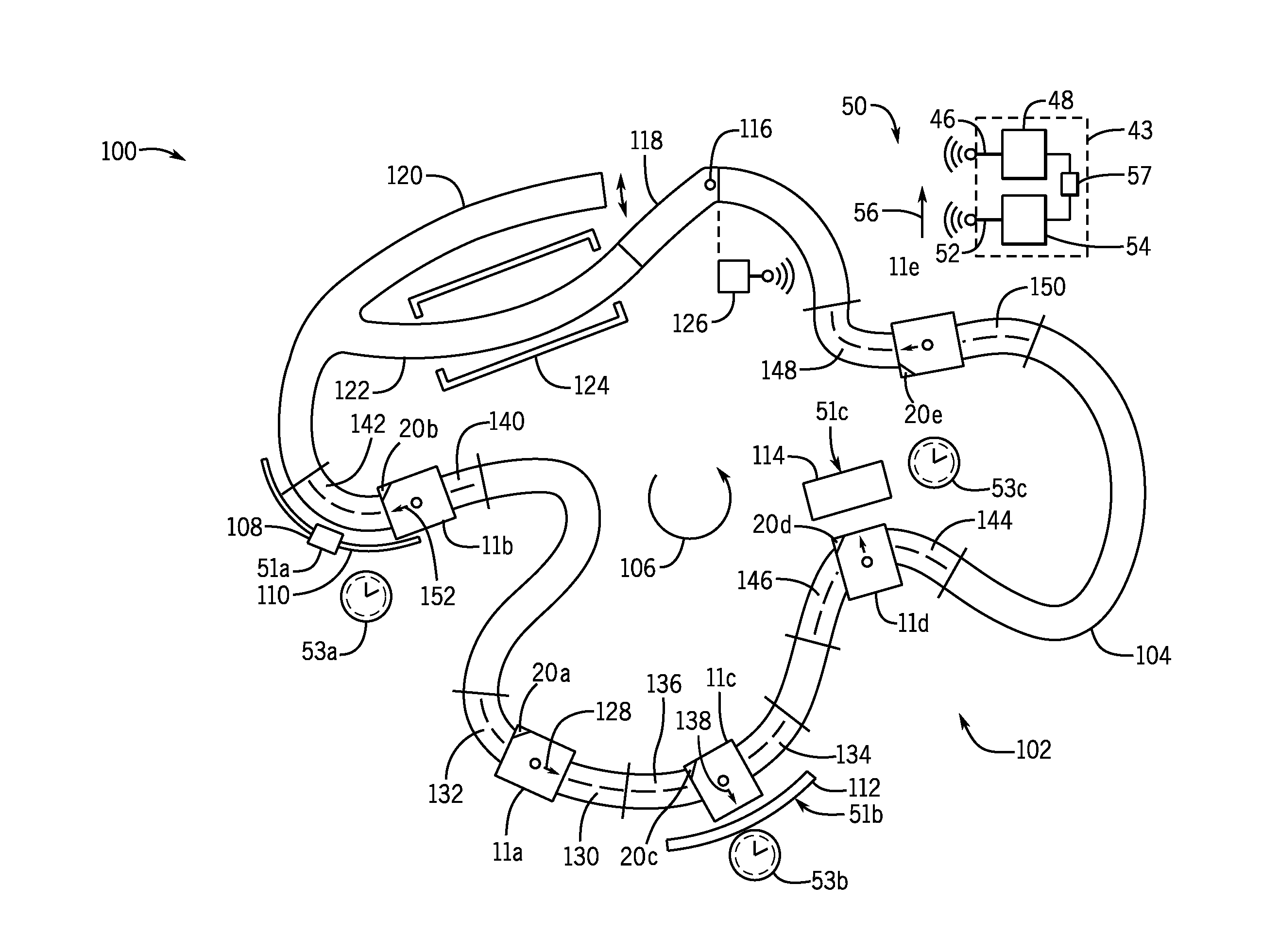
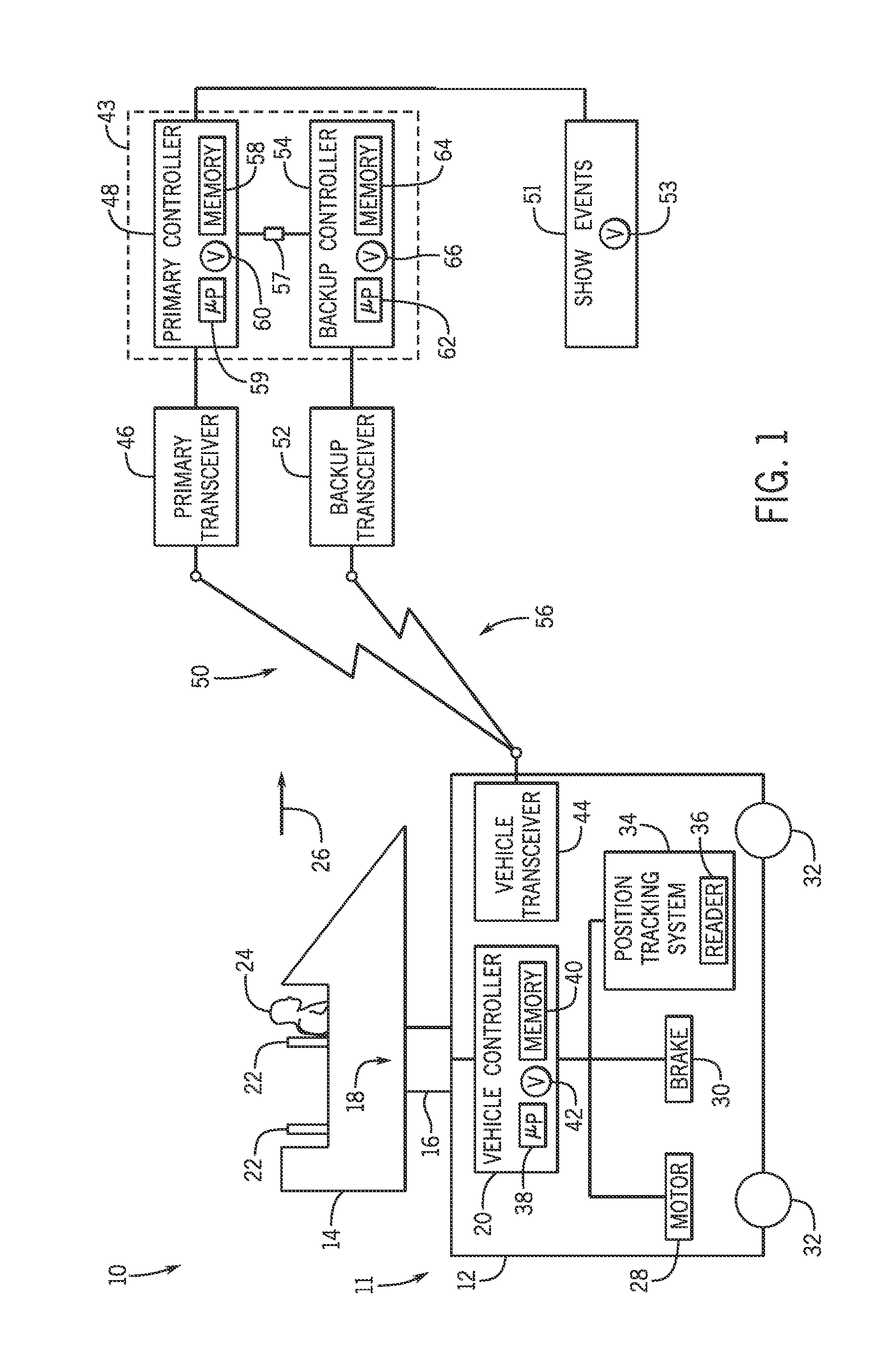
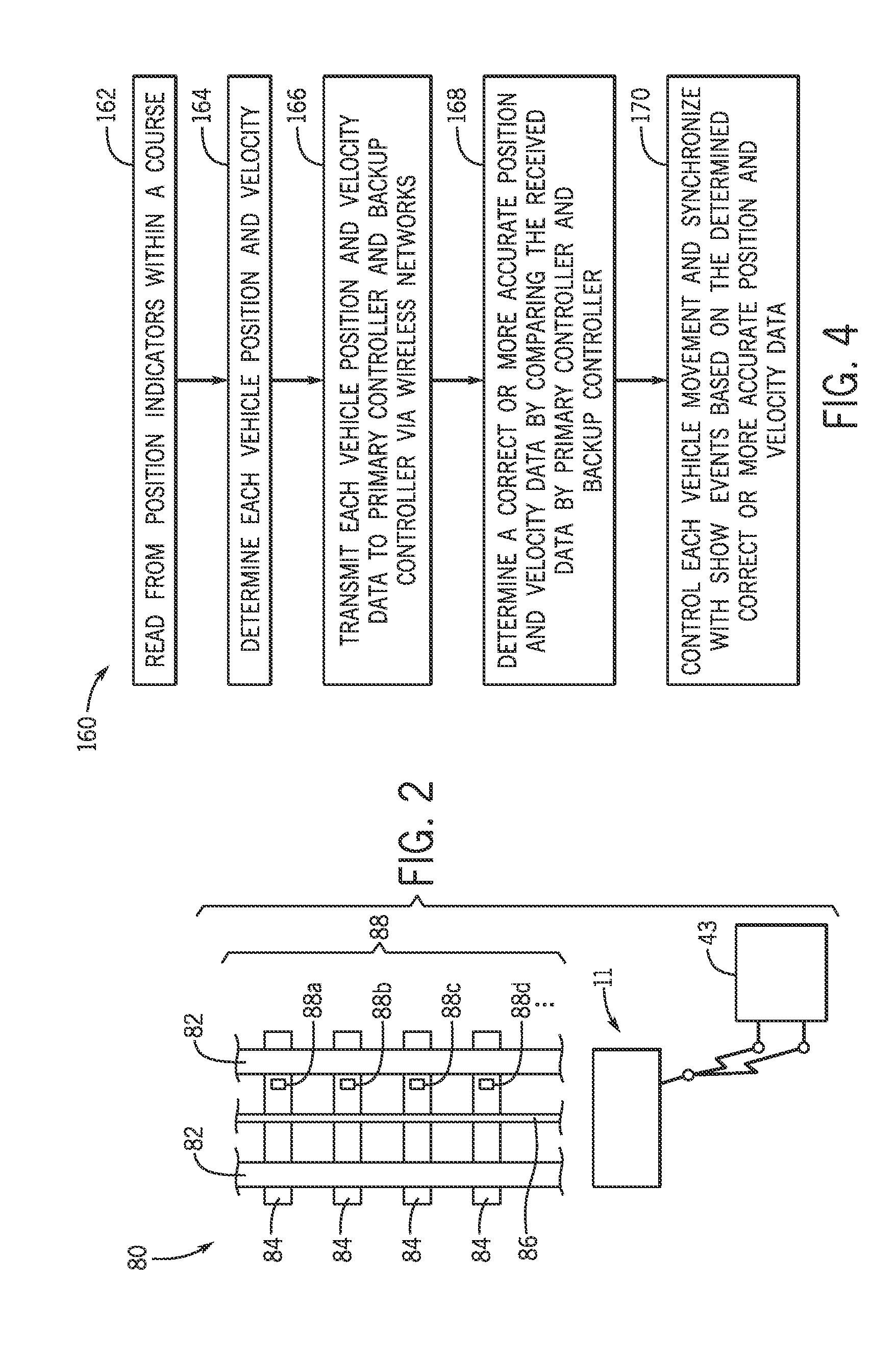
The present patent is about a ride control system for a group of vehicles in a course. The system includes a primary controller and a primary transceiver, along with a primary wireless network that connects them to each other and to the vehicles. The system also includes a backup controller and a backup transceiver, along with a backup wireless network that connects them to the primary controller. The system uses position tracking technology to identify the location of each vehicle and transmits this information to the primary controller and backup controller through the wireless networks. The primary controller and backup controller use a bi-directional circuit to select between the two sets of location information and control the movement of the vehicles based on the chosen location. The technical effect of this system is to provide a coordinated control loop for each vehicle in the group, allowing for better synchronization and control during the ride.

Problems solved by technology

Such control systems often include multiple sensors mounted at various locations along the path with complex wiring for connecting each sensor to the central controller.
It is now recognized that such traditional control systems can be costly to maintain and difficult to integrate.

Method used


Image

  • Virtual attraction controller
  • Virtual attraction controller
  • Virtual attraction controller

Examples


Embodiment Construction

[0013]The present disclosure provides a ride control system including a plurality of ride vehicles positioned within a course and configured to travel within the course. Each of the plurality of ride vehicles includes a vehicle controller configured to control movement of the respective ride vehicle. The movement of each ride vehicle may include external movements, such as running and stopping of the ride vehicle in the course, and internal movements, such as rotation and tilting of a passenger platform with respect to a base of the ride vehicle. Each of the plurality of ride vehicles also may include a position tracking system configured to facilitate identification of a location of the respective ride vehicle within the course. Each vehicle controller is connected to a vehicle transceiver.

[0014]The ride control system also includes a system controller that includes a primary controller and a backup controller. The primary controller is connected to a primary transceiver. A primary...


PUM


Abstract

A ride control system includes a plurality of ride vehicles positioned within a course and configured to travel within the course. Each of the plurality of ride vehicles includes a vehicle controller configured to control movement of a respective one of the plurality of ride vehicles. Each of the plurality of ride vehicles also includes a position tracking system configured to facilitate identification of a location of the respective one of the plurality of ride vehicles within the course. Each of the plurality of ride vehicles further includes a vehicle transceiver in communication with the vehicle controller. The ride control system also includes a primary controller and a primary transceiver in communication with the primary controller. The ride control system further includes a primary wireless network formed by the vehicle transceiver and the primary transceiver to include at least the primary controller and the vehicle controller of each of the plurality of ride vehicles. The primary controller is configured to receive data indicative of the location of each of the plurality of ride vehicles from respective ones of the plurality of ride vehicles via the primary wireless network. The primary controller and the vehicle controller of each of the plurality of ride vehicles are configured to coordinate to provide a control loop for each of the plurality of ride vehicles based on the data indicative of the location of each of the plurality of ride vehicles.

Description

BACKGROUND[0001]The present disclosure relates generally to a system and method for controlling an attraction and, more particularly, to a system and method for controlling motion of a vehicle or a show event in an attraction course.[0002]Theme park or amusement park ride attractions have become increasingly popular. Amusement park rides often include traveling rides, which include ride vehicles that travel along a path (e.g., a railway or a track), fixed rides, which may include a motion base, or combinations thereof. The path of a traveling ride may be situated in different surroundings (e.g., on a mountain top, in a tunnel, under the water). Along the path, there may be different types of show events, such as moving action figures (e.g., animatronics), video screen projections, sound effects, water effects, and so forth. In fixed rides, a movable passenger platform having multiple degrees of freedom is typically situated on a relatively still base. The passenger platform can move...

Claims


Application Information

Patent Timeline
Patent Type & Authority Applications(United States)
IPC IPC(8): A63G31/00G05D1/00
CPCG05D1/0022A63G31/00A63G7/00B61L15/0027B61L23/20B61L25/025B61L27/20G06F9/5061A63G31/02A63J25/00G06F9/4405G06F9/4411
Inventor MAYCOCK, MARK BRUCEVANCE, ERIC
Owner UNIVERSAL CITY STUDIOS LLC
Learn More