
Method for manufacturing an optical preform

a manufacturing method and optical preform technology, applied in glass making apparatus, manufacturing tools, other domestic objects, etc., can solve the problems of increased attenuation, non-circularity of the core of the drawn optical fibre, unround inner diameter of the tube, etc., to improve the optical preform and reduce the non-circular property of the optical preform

Active Publication Date: 2015-11-26
DRAKA COMTEQ BV
View PDF9 Cites 0 Cited by
  • Summary
  • Abstract
  • Description
  • Claims
  • Application Information

AI Technical Summary

Benefits of technology

The present invention provides a method that reduces non-circular properties in an optical preform, resulting in an improved product. This addresses a problem in the art where non-circular properties negatively affected the quality of optical preforms.

Problems solved by technology

One drawback of substrate tubes having deposited layer of glass on the inside surface thereof, for example manufactured according to prior art process using an internal vapour deposition process, is that the inner diameter of these tubes is unround, i.e. not round.
A substrate tube not being circular, for example an oval tube, will result in a non-circularity of the core of the drawn optical fibre.
The above results in a so-called “non-circularity” of the core of the optical fibre after drawing, which is an undesired phenomenon since it leads to increased attenuation.
Non-circularity may, for example, also lead to a single mode fibre having a high polarisation mode dispersion, or may lead to a multimode fibre exhibiting high differential mode delay values due to asymmetry in the core.
Both are undesirable.

Method used


Image

  • Method for manufacturing an optical preform
  • Method for manufacturing an optical preform

Examples


Embodiment Construction

[0035]The following definitions are used in the present description and / or claims to define the stated subject matter. Other terms not cited below are meant to have the generally accepted meaning in the field.

[0036]“hollow substrate tube” as used in the present description means: an elongated tube having a cavity within. Generally, the inside of said tube is provided (or coated) with a plurality of glass layers during the manufacturing of a preform.

[0037]“precursor for a primary preform” as used in the present description means: an intermediate product that will lead to a primary preform after one or more additional process steps.

[0038]“primary preform” as used in the present description means: a solid rod (solid preform) that requires to be externally provided with extra glass before it becomes a final preform.

[0039]“final preform” as used in the present description means: a solid rod (solid composite preform) that an be directly used for drawing of optical fibers therefrom.

[0040]“...


PUM

PropertyMeasurementUnit
pressureaaaaaaaaaa
pressureaaaaaaaaaa
pressureaaaaaaaaaa

Abstract

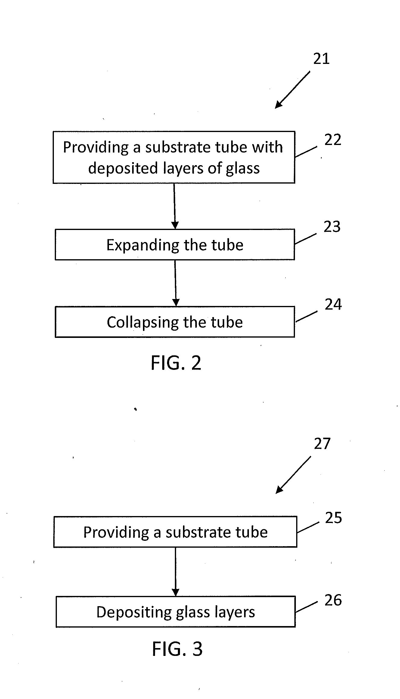
A method for manufacturing an optical preform including the steps of providing a substrate tube having deposited layers of glass on an inside surface thereof, increasing an outer diameter of the substrate tube by means of applying a traversing heat source to heat the substrate tube to above a softening temperature thereof and by providing an internal pressure in the substrate tube higher than an ambient pressure, and collapsing the substrate tube of increased outer diameter by means of applying the traversing heat source to heat the substrate tube to above the softening temperature thereof such that an optical preform is manufactured.

Description

TECHNICAL FIELD AND BACKGROUND OF THE INVENTION[0001]The present invention relates to a method for manufacturing an optical preform including the steps of providing a substrate tube having deposited layers of glass, on the inside surface thereof, and collapsing the substrate tube by means of applying a traversing heat source to heat the substrate tube to above its softening temperature such that an optical preform is manufactured.[0002]Generally, in the field of optical fibers, multiple thin films of glass are deposited on the inside surface of a substrate tube. Glass-forming gases (viz. doped or undoped reactive gases) are introduced into the interior of the substrate tube from one end (supply side of the substrate tube). Doped or undoped glass layers are deposited onto the interior surface of the substrate tube. The gases are discharged or removed from the other end of the substrate tube, optionally by the use of a vacuum pump (discharge side of the substrate tube). The vacuum pum...

Claims


Application Information

Patent Timeline
Patent Type & Authority Applications(United States)
IPC IPC(8): C03B37/07C03B37/018C03B37/012
CPCC03B37/07C03B37/01248C03B2203/00C03B37/018C03B37/0124C03B37/01861C03B37/01869
Inventor MILICEVIC, IGORKRABSHUIS, GERTJANGERHARTS, PETERHARTSUIKER, JOHANNES ANTOONVAN STRALEN, MATTHEUS JACOBUS NICOLAAS
Owner DRAKA COMTEQ BV
Learn More