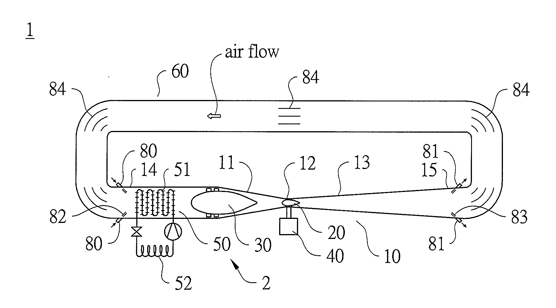
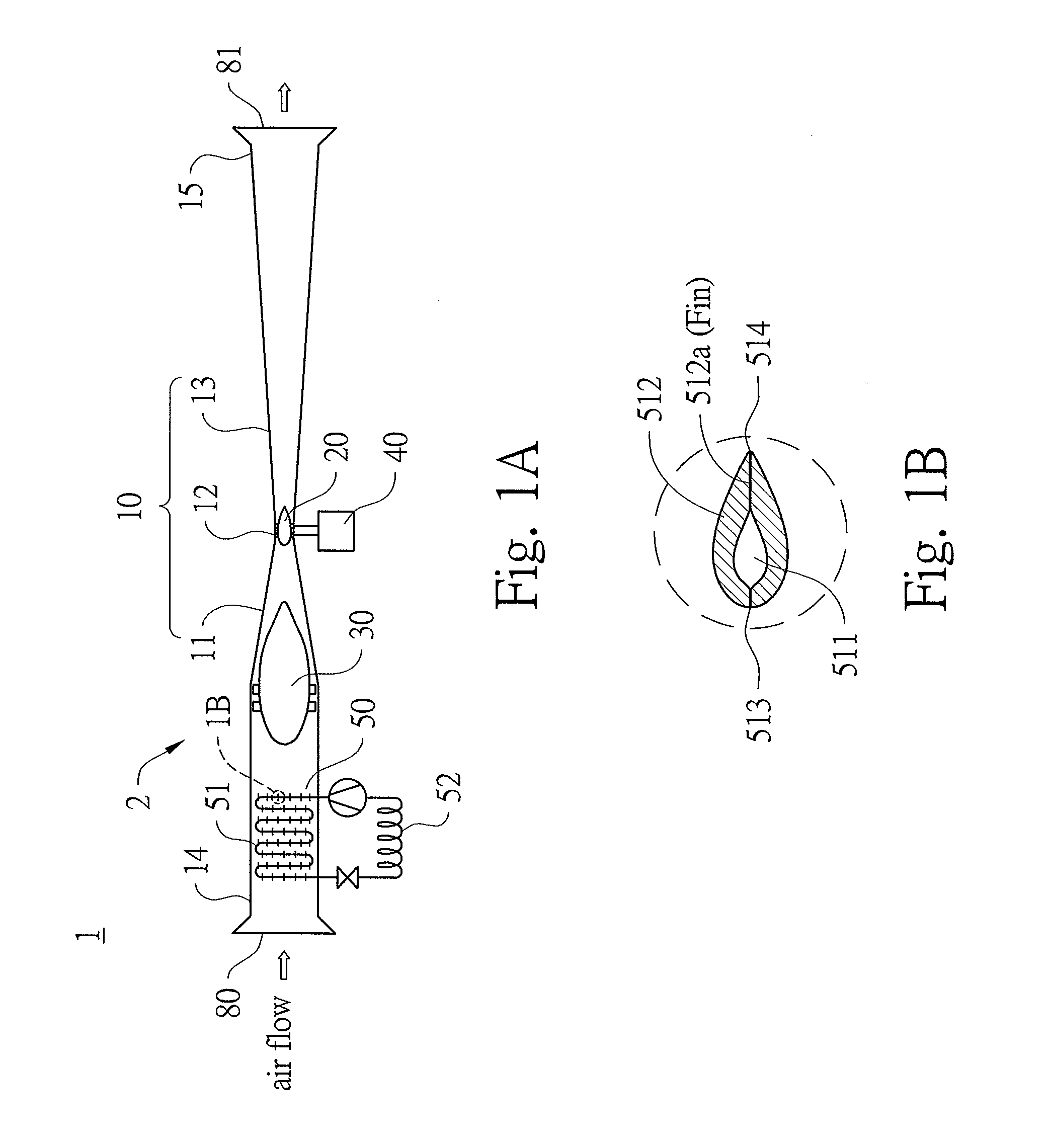
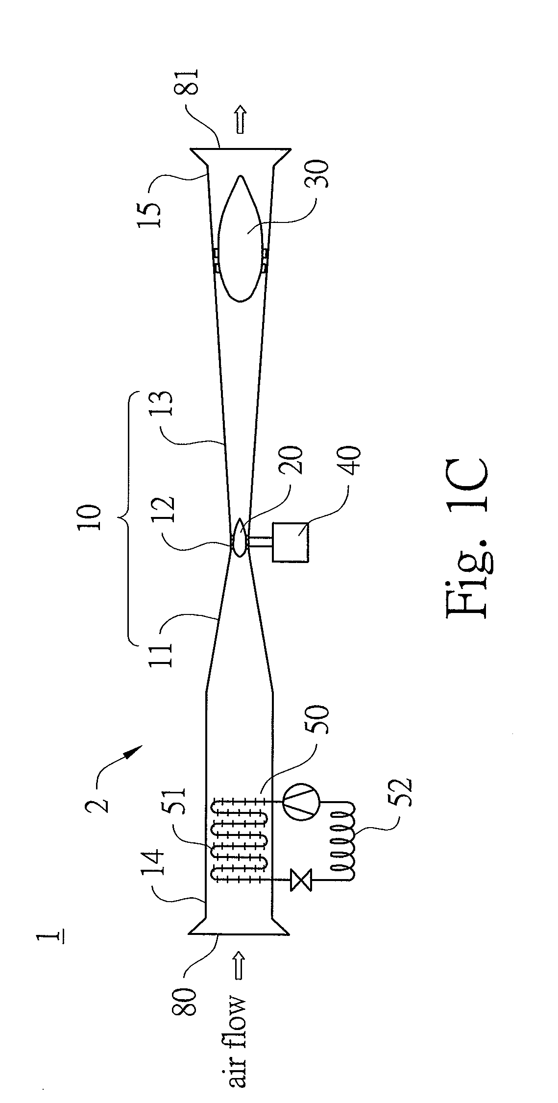
Clean energy generation system
a generation system and energy technology, applied in the direction of electric generator control, machines/engines, mechanical equipment, etc., can solve the problems of global rethinking and reorientation of the future of mankind, and the contamination of the storage site of radioactive nuclear waste, so as to achieve less pollution and high efficiency
- Summary
- Abstract
- Description
- Claims
- Application Information
AI Technical Summary
Benefits of technology
Problems solved by technology
Method used
Image
Examples
working example 1
Compression Ratio P2 / P1=2, Expansion Ratio P3 / P4=3
A. At Compressor Section:
[0106]Assume: 1. Heat pump heats up the air / gas-flow at upstream of air / gas compressor from 10° C. to 35° C. (=10° C.+25° C. temp. lift, the heat source may be ambient air / gas or shallow geothermal heat source of about 50 m depth.), thus T1=35° C.=308K
Assume: 2. Compression ratio of air / gas compressor:
P2P1=2,thusT2=T1(P2P1)(1-11.4)=T1(2)(27)=308K*1.219=375.5K=102.5°C.
Inlet / Outlet air / gas temperature difference:
ΔT12=T2−T1=375.5K−308K=67.5K
Thus, WCPS=MCPΔT12=67.5MCP
B. At Turbine Section:
[0107]Assume expansion ratio
P3P4
is enlarged from 2 to 3, caused by huge suction pressure from the compressor of the next combination at downstream in tandem, thus:
P4P3=13asT3=T2=375.5K=102.5°C.,thus,T4=T3(P4P3)(1-11.4)=T3(13)(27)=375.5K*0.730=274.1K=1.1°C.ΔT34=T3-T4=375.5K-274.1K=101.4KThus,Wtb=MCPΔT34=101.4MCP=101.4*WCPS67.5=1.502WCPSWuseful=Wtb-(WCPS+WHP)=(1.502-(1+0.15))WCPS=0.352WCPSEnergyEfficiency=WusefulInputEnergy=Wusef...
working example 2
Compression Ratio P2 / P1=3, Expansion Ratio P3 / P4=6
A. At Compressor Section:
[0108]Assume: 1. Heat pump heats up the air / gas-flow at upstream of air / gas compressor from 35° C. to 60° C. (=35° C.+25° C. temp. lift, this may come from geothermal heat source at about 800 m depth.), thus T1=60° C.=333K
Assume: 2. Compression ratio of air / gas compressor:
P2P1=3,thusT2=T1(P2P1)(1-11.4)=T1(3)(27)=333K=1.369=455.9K=182.9°C.
Inlet / Outlet air / gas temperature difference:
ΔT12=T2−T1=455.9K−333K=122.9K
Thus, WCPS=MCPΔT12=122.9MCP
B. At Turbine Section:
[0109]Assume expansion ratio
P3P4
is enlarged from 3 to 6, caused by huge suction pressure from the compressor of the next combination at
downstream in tandem, thus:
P4P3=16asT3=T2=455.9K=182.9°C.,thus,T4=T3(P4P3)(1-11.4)=T3(16)(27)=375.5K*0.599=273.1K=0.1°C.ΔT34=T3-T4=455.9K-273.1K=182.8KThus,Wtb=MCPΔT34=182.8MCP=182.8*WCPS122.9=1.487WCPSWuseful=Wtb-(WCPS+WHP)=(1.487-(1+0.15))WCPS=0.337WCPSEnergyEfficiency=WusefulInputEnergy=WusefulWCPS+WHP=0.3371+0.15=29.30...
working example 3
Compression Ratio P2 / P1=5, Expansion Ratio P3 / P4=13
A. At Compressor Section:
[0110]Assume: 1. Heat pump heats up the air / gas-flow at upstream of air / gas compressor from 60° C. to 85° C. (=60° C.+25° C. temp. lift, this may come from geothermal heat source of moderately deep type at about 1500 m depth.), thus T1=85° C.=358K
Assume: 2. Compression ratio of air / gas compressor:
P2P1=5,thusT2=T1(P2P1)(1-11.4)=T1(5)(27)=358K*1.585=567.4K=294.4°C.
Inlet / Outlet air / gas temperature difference:
ΔT12=T2−T1=567.4K−358K=209.4K
Thus, WCPS=MCPΔT12=209.4MCP
B. At Turbine Section:
[0111]Assume expansion ratio
P3P4
is enlarged from 6 to 13, caused by huge suction pressure from the compressor of the next combination at downstream in tandem, thus:
P4P3=113asT3=T2=567.4K=294.4°C.,thus,T4=T3(P4P3)(1-11.4)=T3(113)(27)=567.4K*0.480=272.4K=-0.6°C.3ΔT34=T3-T4=567.4K-272.4K=295.0KThus,Wtb=MCPΔT34=295.0MCP=295.0*WCPS209.4=1.409WCPSWuseful=Wtb-(WCPS+WHP)=(1.409-(1+0.15))WCPS=0.259WCPSEnergyEfficiency=WusefulInputEnergy=W...
PUM
 Abstract
Description
Claims
Application Information
 - R&D Engineer
- R&D Manager
- IP Professional
- Industry Leading Data Capabilities
- Powerful AI technology
- Patent DNA Extraction
Browse by: Latest US Patents, China's latest patents, Technical Efficacy Thesaurus, Application Domain, Technology Topic.
© 2024 PatSnap. All rights reserved.Legal|Privacy policy|Modern Slavery Act Transparency Statement|Sitemap


