Pneumatic sensing actuator

a technology of pneumatic sensing and actuators, which is applied in the direction of machines/engines, manufacturing tools, other domestic articles, etc., can solve the problems of difficult position control, system bulky, heavy, complex, outweighing any potential advantages

Active Publication Date: 2015-11-26
CHILDRENS MEDICAL CENT CORP +1
View PDF1 Cites 18 Cited by
  • Summary
  • Abstract
  • Description
  • Claims
  • Application Information

AI Technical Summary

Problems solved by technology

One of the drawbacks of these pneumatic actuators is that they can be difficult to control with respect to position (contraction length) and force (contraction force) due to their inherent nonlinear behavior.
However, these extrinsic sensors make the system bulky, heavy, and complex, outweighing any potential advantages of using relatively small and light weight pneumatics for actuation.

Method used


Image

  • Pneumatic sensing actuator
  • Pneumatic sensing actuator
  • Pneumatic sensing actuator

Examples


examples

[0060]One example of an actuator according to the invention and its intermediate fabrication stages are shown in FIGS. 10(a) and 10(b). FIG. 10(a) shows the front and back sides of the completed device. FIG. 10(b) shows the fibers and a sensor layer bonded in 3D printed mold. Detailed views of one completed prototype according to the invention are shown in FIGS. 11(a) and 11(b). FIG. 11(a) shows front side with the sensor layer over the fiber layer. FIG. 11(b) shows the back side with the fiber layer over the sensor layer. The actuator shown in FIGS. 10(a), 10(b) and 11(a), 11(b) has a single unit zero-volume air chamber and embedded microchannels in multiple flat layers. By connecting or fabricating the actuators in series along their axis, a group of multiple flat actuators can be made, as shown in FIG. 12. The example shown in FIG. 12 has the capability of more than 25% contraction. While a serial configuration of multiple muscles increases the contraction length, a parallel conf...


PUM

PropertyMeasurementUnit
diameteraaaaaaaaaa
diameteraaaaaaaaaa
pressuresaaaaaaaaaa

Abstract

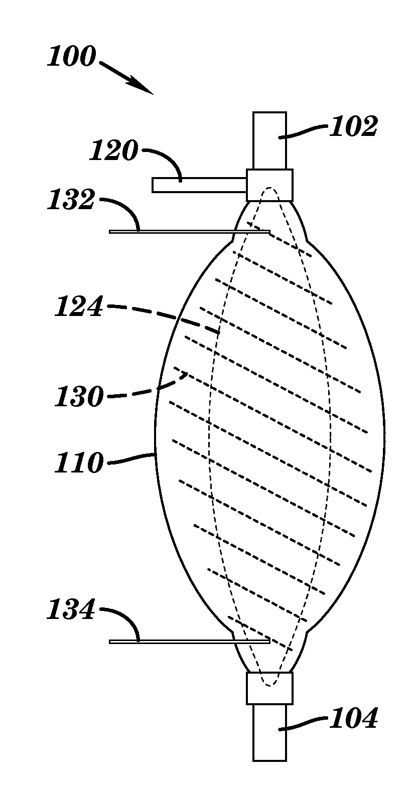
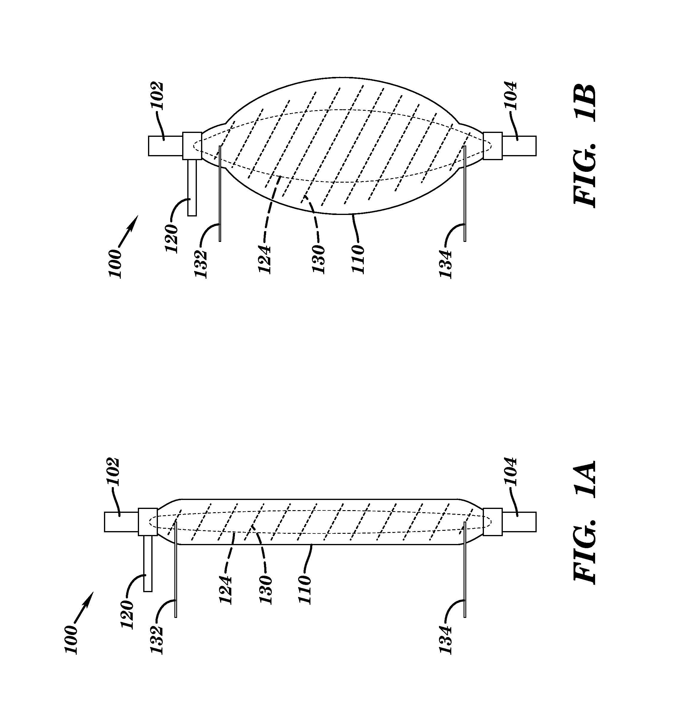
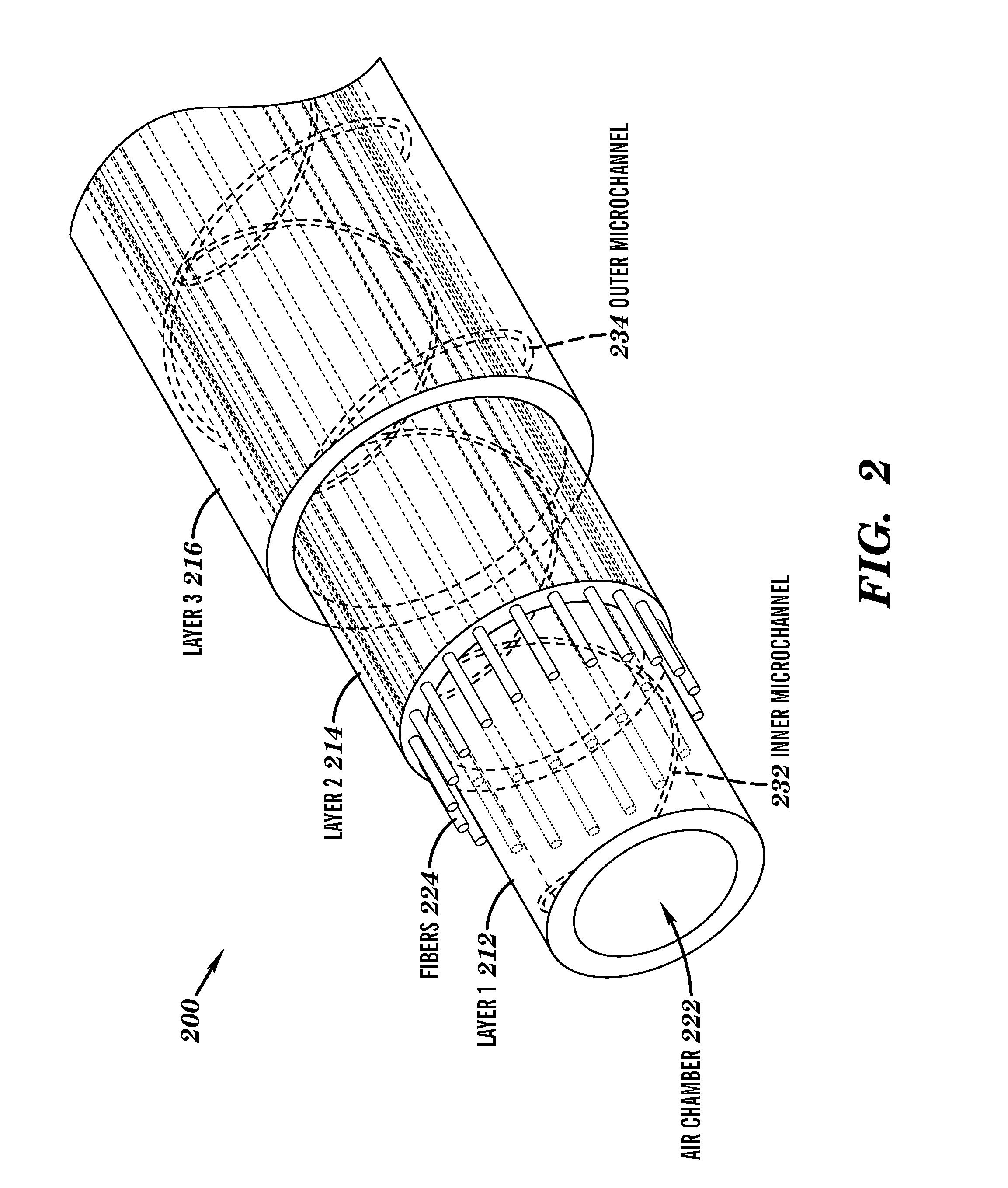
A pneumatic artificial muscle (PAM) actuator body can be formed from an elastic material that includes an inflatable chamber and a restraining component, such as flexible, but inextensible fibers, that causes the actuator to contract when the chamber is inflated with fluid (e.g., air or water). The actuator body can be cylindrical or flat. The actuator body can include a sensor layer formed of an elastic material including a microchannel filled with a conductive fluid to sense the expansion of the actuator body. The sensor layer can be configured to expand when the actuator body is inflated causing the electrical resistance of the conductive fluid to change. A sensor layer between the actuator body and restraining component can be used to measure changes in the contraction force of the actuator and a sensor layer outside of the restraining component can be used to measure changes in the length of the actuator.

Description

CROSS-REFERENCE TO RELATED APPLICATIONS[0001]This application claims benefit under 35 U.S.C. § 119(e) of the U.S. Provisional Application No. 61 / 754,681, filed Jan. 21, 2013, the contents of which are incorporated herein by reference in their entirety.[0002]This application is related to U.S. patent application Ser. No. 12 / 945,014, entitled Stretchable Two-Dimensional Pressure Sensor, now U.S. Pat. No. 8,316,719, and PCT Patent Application no. PCT / US2012 / 053569, designating the US, entitled Actively Controlled Wearable Orthotic Devices and Active Modular Elastomer Sleeve for Wearable Orthotic Devices, the contents of each application is hereby incorporated by reference in its entirety.GOVERNMENT SUPPORT[0003]This invention was made with government support under grant no. CNS 0932015 awarded by U.S. National Science Foundation. The government has certain rights in the invention.REFERENCE TO MICROFICHE APPENDIX[0004]Not ApplicableBACKGROUND[0005]1. Technical Field of the Invention[000...

Claims


Application Information

Patent Timeline
Patent Type & Authority Applications(United States)
IPC IPC(8): F15B15/10B29D23/00F15B15/28
CPCF15B15/103F15B15/2815B29D23/001B29K2995/0005B29K2101/00B29K2105/14B29K2105/24B29D2009/00B29C39/123B32B3/00
Inventor PARK, YONG-LAEWOOD, ROBERT J.SANTOS, JOBIMGOLDFIELD, EUGENE C.
Owner CHILDRENS MEDICAL CENT CORP
Why Eureka
Try Eureka