
Finite element mesh customisation

a finite element and mesh technology, applied in the field of generating customised finite element meshes, can solve the problems of inability to accurately model the actual components of fea performed on generic meshes, inability to accurately model the actual components, and inability to accurately model the generic meshes. achieve the effect of large effort, high curvature, and rapid expansion of the library of shapes

Active Publication Date: 2015-11-26
ROLLS ROYCE PLC
View PDF3 Cites 14 Cited by
  • Summary
  • Abstract
  • Description
  • Claims
  • Application Information

AI Technical Summary

Benefits of technology

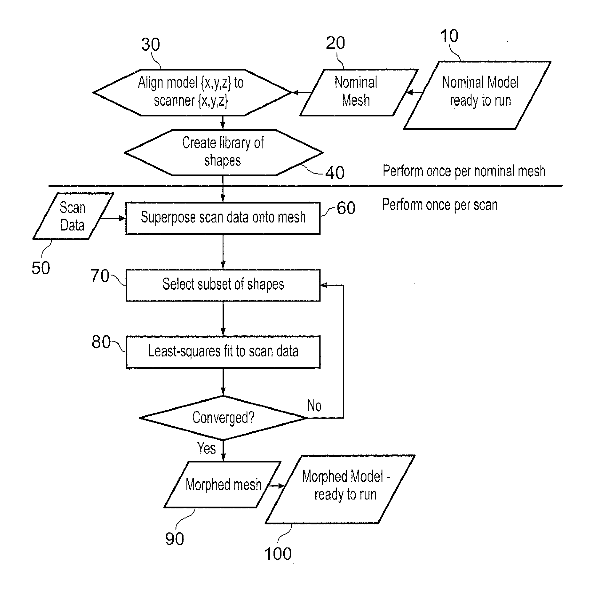
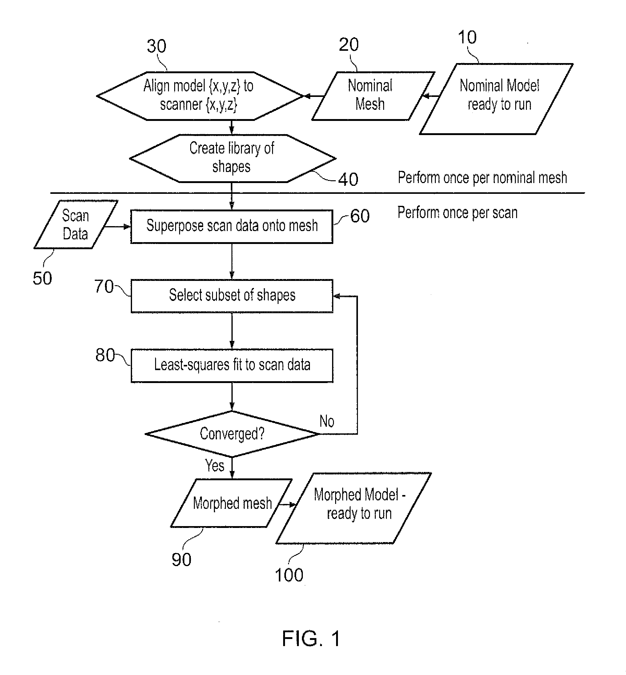
The patent describes a method for creating a customised finite element mesh for a specific component by reducing or eliminating variations in the shape of the component using a combination of displacement shapes. The system includes a library of displacement shapes that can be applied to a generic mesh to create the customised mesh. The process involves superposing the actual component onto a virtual mesh, mapping the surface of the component onto the mesh, and determining the combination of displacement shapes that removes shape variations. The final customised mesh reduces the impact of any shape variations in the component on its overall performance. The system also includes a display device for displaying the different versions of the mesh and the determined displacement shapes.

Problems solved by technology

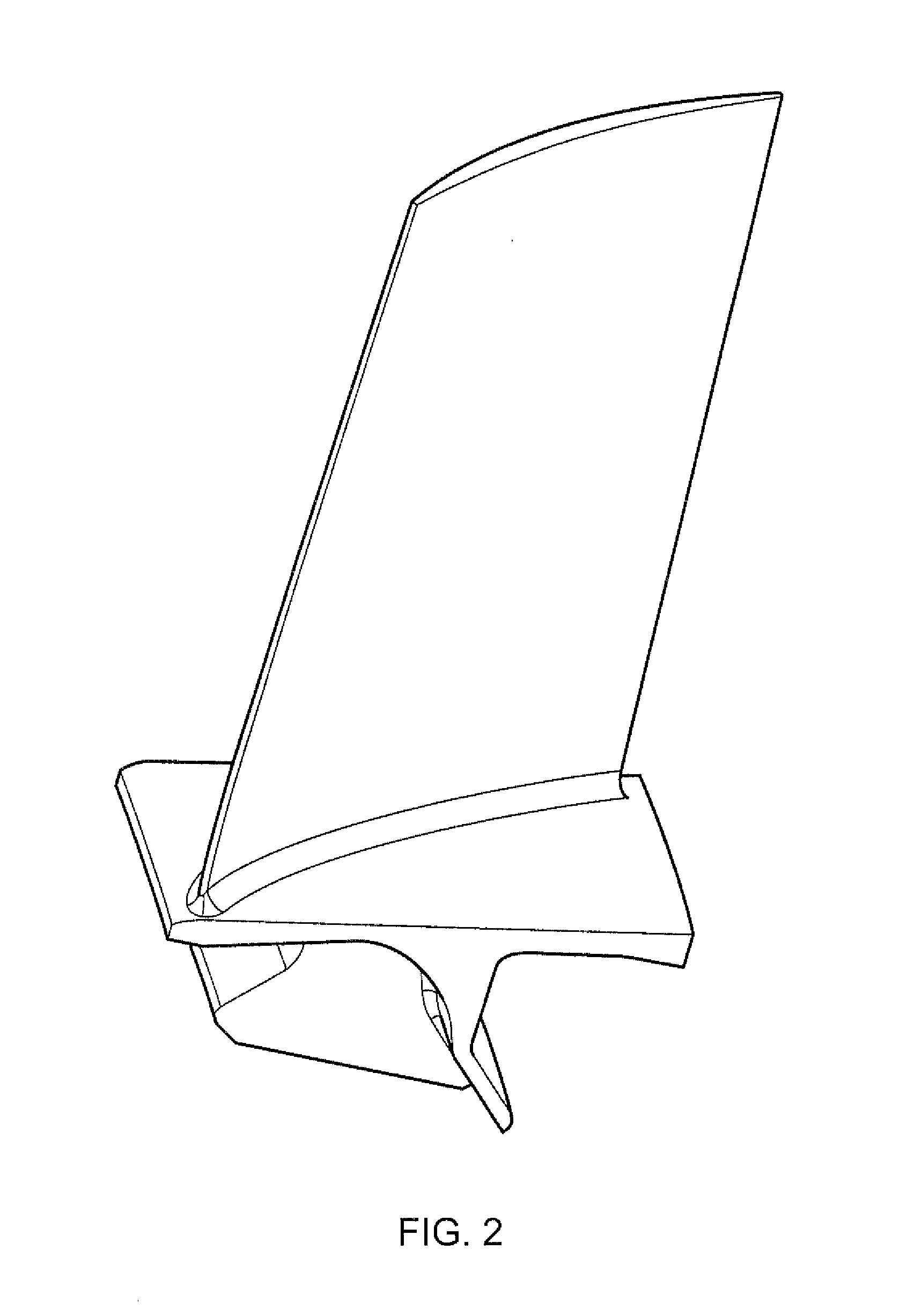
Particularly in respect of complex-shaped components, such as gas turbine engine (GTE) blades and vanes, a considerable amount of effort can thus go into meshing the component.
If the variations are small, then the differences between the generic mesh and the actual components may be immaterial.
However, if the variations are not small a problem can then arise that FEA performed on the generic mesh may not accurately model the actual components.
A similar problem occurs if it is wanted to use FEA to quantify the effect of shape variations between actual components.
However, a simple distortion can reduce the quality of the mesh, e.g. by increasing element skewnesses and aspect ratios, and disturbing smooth size transitions.
However, re-meshing can be labour intensive and time-consuming.

Method used


Image

  • Finite element mesh customisation
  • Finite element mesh customisation
  • Finite element mesh customisation

Examples


Embodiment Construction

[0040]The ensuing description provides preferred exemplary embodiment(s) only, and is not intended to limit the scope, applicability or configuration of the invention. Rather, the ensuing description of the preferred exemplary embodiment(s) will provide those skilled in the art with an enabling description for implementing a preferred exemplary embodiment of the invention, it being understood that various changes may be made in the function and arrangement of elements without departing from the scope of the invention.

[0041]Specific details are given in the following description to provide a thorough understanding of the embodiments. However, it will be understood by one of ordinary skill in the art that embodiments maybe practiced without these specific details. For example, well-known circuits, processes, algorithms, structures, and techniques may be shown without unnecessary detail in order to avoid obscuring the embodiments.

[0042]Also, it is noted that embodiments may be describe...


PUM


Abstract

Method of providing the generic finite element mesh; providing a library of displacement shapes of generic mesh, each displacement shape being applicable to the generic mesh to generate altered mesh; providing a set of scanned data points which map the surface of the actual component, each scanned data point defining the spatial position of a respective location on the surface of the actual component; superposing the scanned data points on the surface of generic mesh; projecting scanned data points onto respective proximal surface locations of generic mesh to form a set of near data points, each near data point defining the spatial position of respective location on the surface of the generic mesh; determining a combination of the displacement shapes; and applying the combination of displacement shapes to the generic mesh to generate a customised finite element mesh for the actual component.

Description

FIELD OF THE INVENTION[0001]The present invention relates to a method of generating a customised finite element mesh for a component.BACKGROUND OF THE INVENTION[0002]Finite element analysis (FEA) is widely used to model and solve engineering problems relating to complex systems such as three-dimensional non-linear structural design and analysis. FEA derives its name from the manner in which the geometry of the object under consideration is specified. Basically, FEA computer software is provided with a model of the geometric description and the associated material properties at each point within the model. In this model, the geometry of the system under analysis is represented by solids, shells and beams of various sizes, which are called elements. The vertices of the elements are referred to as nodes. The model is comprised of a finite number of elements, which are assigned a material name to associate the elements with the material properties. The model thus represents the physical...

Claims


Application Information

Patent Timeline
Patent Type & Authority Applications(United States)
IPC IPC(8): G06T17/20
CPCG06T17/20G06T19/20G06T2219/2021G06T17/205G06F30/23
Inventor DATE, DAVID LEONARDBATES, RONALD ANTHONY
Owner ROLLS ROYCE PLC
Learn More