Flexible tether position tracking camera inspection system for visual inspection of off line industrial gas turbines and other power generation machinery

a technology of tether position and tracking camera, which is applied in the direction of television system, machines/engines, instruments, etc., can solve the problems of difficult positioning of inspection apparatus, narrow confines of passages surrounding stationary vanes, and inflexible or limpness to prevent controlled positioning within passages

Inactive Publication Date: 2015-11-26
SIEMENS ENERGY INC
View PDF16 Cites 32 Cited by
  • Summary
  • Abstract
  • Description
  • Claims
  • Application Information

AI Technical Summary

Benefits of technology

[0015]This and other objects are achieved in one or more embodiments of the invention by a camera scope inspection system with a flexible tether mounted camera head and a camera head position sensing system that inferentially determines the three dimension (3D) position of the camera head. Camera head position data are correlated with camera image data by a controller. In this manner correlated internal inspection image data and corresponding position data are available for future analysis and image tracking similar to data processing performed with data gathered from multi-axis motorized inspection systems, with the advantages of being able to maneuver manually the tethered camera scope into confined spaces not readily accessible by the multi-axis systems.

Problems solved by technology

The narrow confines of passages surrounding stationary vanes often will not facilitate passage of traditional inspection scope systems.
Inspection apparatus positioning is challenging due to the complex, often tortuous manipulation paths between components in a gas turbine.
The inspection scope camera delivery system must be sufficiently flexible to insert through tight confined passages, yet not too flexible or limp to prevent controlled positioning within the passages.
Unlike the aforementioned motorized multi-axis inspection system that is described in United States patent application publication number 2013 / 0192353, the flexible tethered camera inspection system does not provide camera head position / orientation information that can be advantageously combined with the optical image information for future analysis or composite image generation.

Method used


Image

  • Flexible tether position tracking camera inspection system for visual inspection of off line industrial gas turbines and other power generation machinery
  • Flexible tether position tracking camera inspection system for visual inspection of off line industrial gas turbines and other power generation machinery
  • Flexible tether position tracking camera inspection system for visual inspection of off line industrial gas turbines and other power generation machinery

Examples


Embodiment Construction

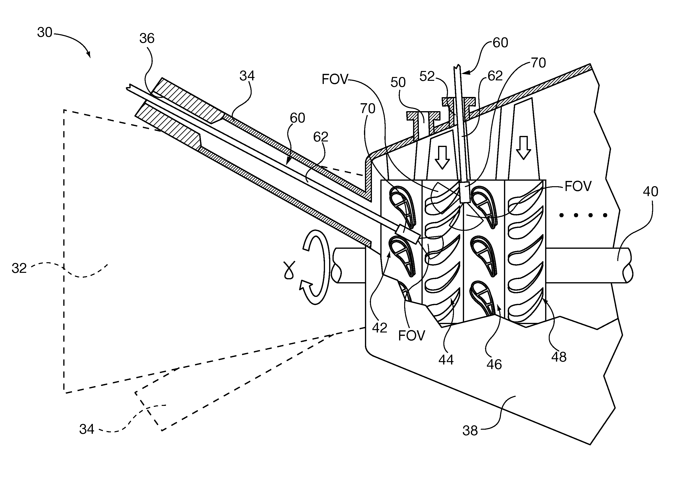
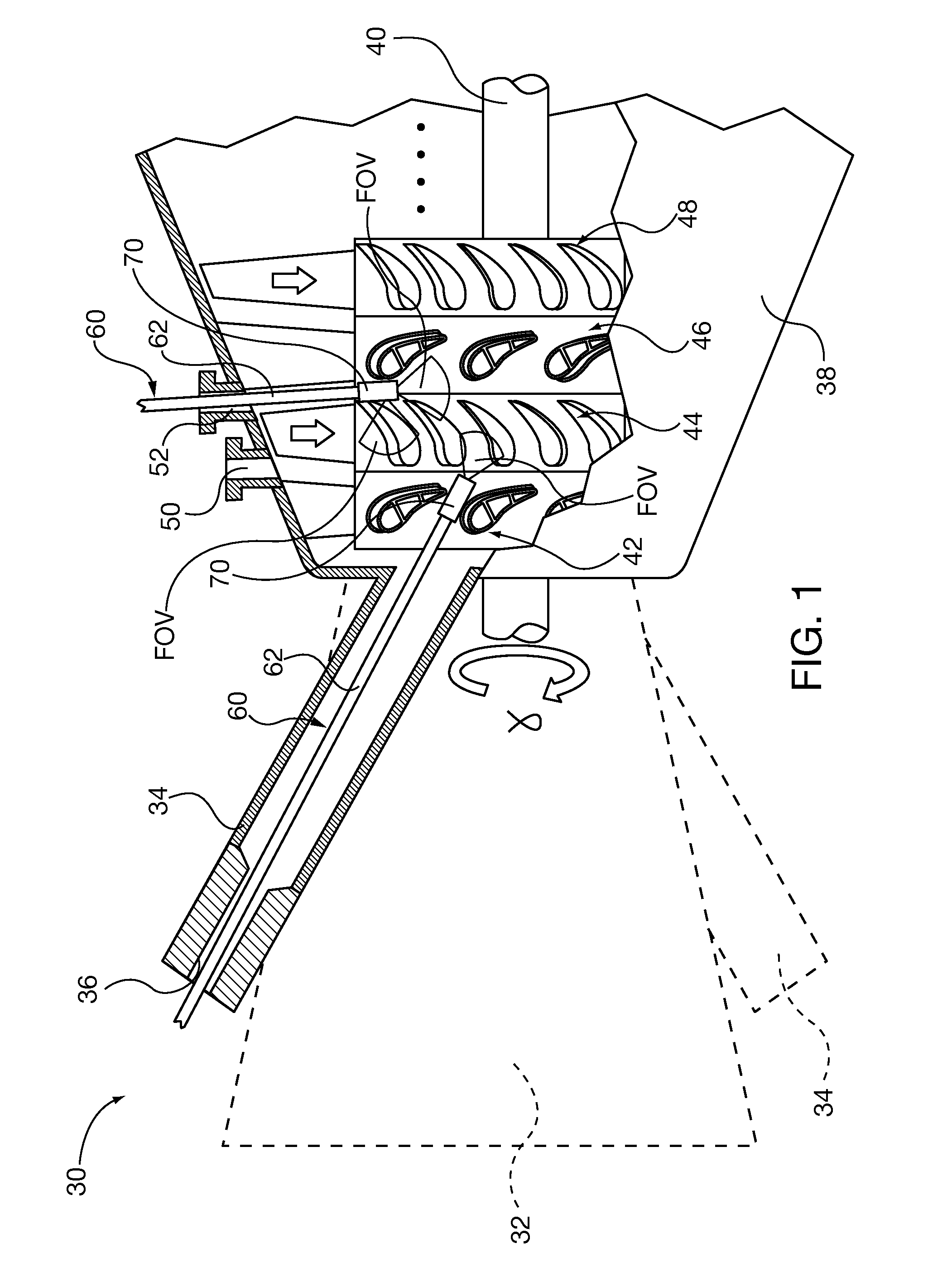
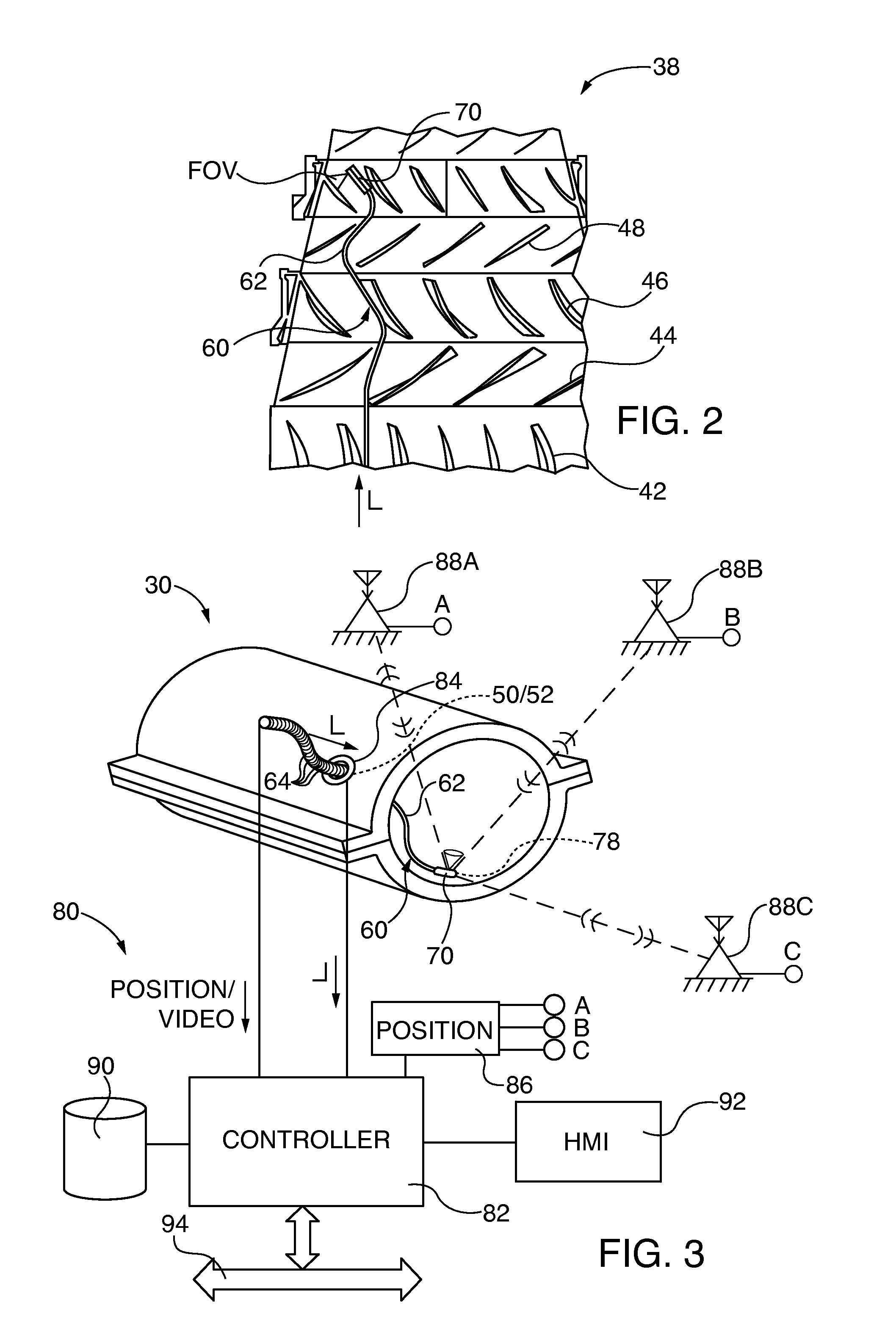
[0031]After considering the following description, those skilled in the art will clearly realize that the teachings of the present invention can be readily utilized in a camera scope inspection system with a flexible, tether mounted camera head that is maneuverable in confined internal cavities of power generation machinery. A camera head position sensing system inferentially determines the three dimension (3D) position of the camera head within the inspected machinery. Camera head position data are correlated with camera image data by a controller. In this manner correlated internal inspection image data and corresponding position data are available for future analysis and image tracking.

[0032]Referring to FIGS. 1-3, embodiments of the invention facilitate automated off-line remote visual inspection of gas turbine 30 internal components, including the compressor section 32, the combustor section 34, the turbine section 38 Row 1 and Row 2 fixed vanes 42, 46; leading Row 1 and Row 2 ...


PUM


Abstract

A camera scope inspection system with a flexible, tether mounted camera head that is maneuverable in confined internal cavities of power generation machinery. A camera head position sensing system inferentially determines the three dimension (3D) position of the camera head within the inspected machinery. Camera head position data are correlated with camera image data by a controller. In this manner correlated internal inspection image data and corresponding position data are available for future analysis and image tracking.

Description

CROSS-REFERENCE TO RELATED APPLICATIONS[0001]This application incorporates by reference the entire contents of each of co-pending U.S. patent applications:[0002]“Flexible Linkage Camera System And Method For Visual Inspection Of Off Line Industrial Gas Turbines And Other Power Generation Machinery”, filed Aug. 21, 2013, Ser. No. 13 / 972,332, United States patent application publication number 2014 / 0055596;[0003]“System And Method For Visual Inspection And 3D White Light Scanning Of Off-Line Industrial Gas Turbines And Other Power Generation Machinery”, filed Aug. 21, 2013, Ser. No. 13 / 97200, United States patent application publication number 2013 / 0335530; and[0004]“System And Method For Automated Optical Inspection Of Industrial Gas Turbines And Other Power Generation Machinery With Multi-Axis Inspection Scope”, filed Jan. 31, 2012, Ser. No. 13 / 362,352, United States patent application publication number 2013 / 0192353.BACKGROUND OF THE INVENTION[0005]1. Field of the Invention[0006]Th...

Claims


Application Information

Patent Timeline
Patent Type & Authority Applications(United States)
IPC IPC(8): H04N7/18H04N5/225
CPCH04N7/183H04N2005/2255H04N5/2251F01D21/003G02B23/2476G02B23/2484H04N23/50G01N21/954H04N23/555
Inventor HATCHER, JR., CLIFFORDRUHGE, FORREST R.
Owner SIEMENS ENERGY INC
Why Eureka
Try Eureka