Fuel injection system including a fuel-guiding component, a fuel injector, and a connecting element

a fuel injection system and connecting element technology, applied in the direction of low pressure fuel injection, mechanical equipment, machines/engines, etc., can solve the problems of undesirable noise generation, objectionable contribution to the overall noise of the engine, and the transmission of vibrations from the fuel injector to the connecting piece via the snap ring, so as to simplify the design of the contact surface, in particular on the fuel connector.

Inactive Publication Date: 2015-12-03
ROBERT BOSCH GMBH
View PDF8 Cites 10 Cited by
  • Summary
  • Abstract
  • Description
  • Claims
  • Application Information

AI Technical Summary

Benefits of technology

[0014]Furthermore, it is advantageous that at least the contact surface of the inner side of the base body has a cylinder jacket shape. This results in advantages when the stress occurs mainly perpendicularly with respect to the contact surface, in particular in the radial direction.
[0015]However, it is also advantageous that at least the contact surface of the inner side of the base body has a concave profile. In this design, even forces having different directions, in particular having an axial component, may be reliably absorbed. This allows improved suspension in such cases.
[0016]In addition, the decoupling element may advantageously include at least one elastic layer and at least one protective layer, in particular a metallic protective layer, the at least one elastic layer and the at least one protective layer being layered in the radial direction. In particular, an elastic layer may be situated between two metallic protective layers. On the one hand, the contact between the fuel injector and the decoupling element, and between the base body and the decoupling element, may thus take place at the resistant protective layers. On the other hand, homogeneous stress on the elastic material of the elastic layer may also be achieved. In addition, the design of the contact surfaces, in particular on the fuel connector, may thus be simplified, since force is distributed over a larger cross-sectional area via the protective layer.
[0017]It is also advantageous that the decoupling element is made, at least essentially, of an...

Problems solved by technology

The design of the fuel injection device known from published German patent application document DE 10 2005 020 380 A1 has the disadvantage that vibrations may be transmitted from the fuel injector to the connecting piece via the snap ring.
This may result in undesirable noise generation.
In particular for electromagnetic high-pressure injectors, which are used in gasoline engines having direct injection, a noticeable, objectionab...

Method used


Image

  • Fuel injection system including a fuel-guiding component, a fuel injector, and a connecting element
  • Fuel injection system including a fuel-guiding component, a fuel injector, and a connecting element
  • Fuel injection system including a fuel-guiding component, a fuel injector, and a connecting element

Examples


Embodiment Construction

[0026]In the following description, with reference to the appended drawings, corresponding elements are provided with the same reference numerals.

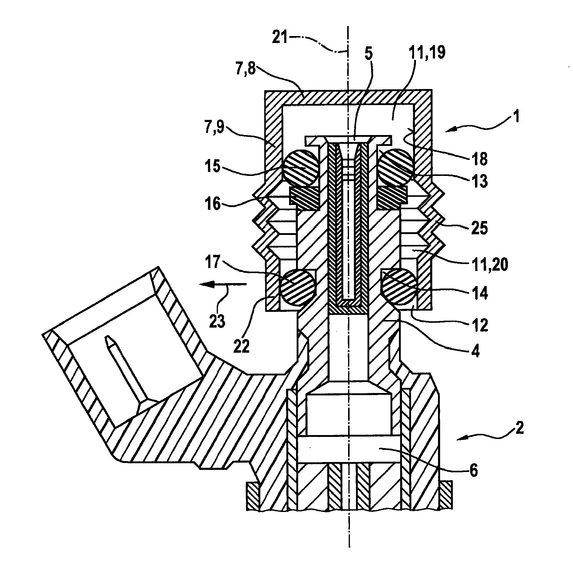
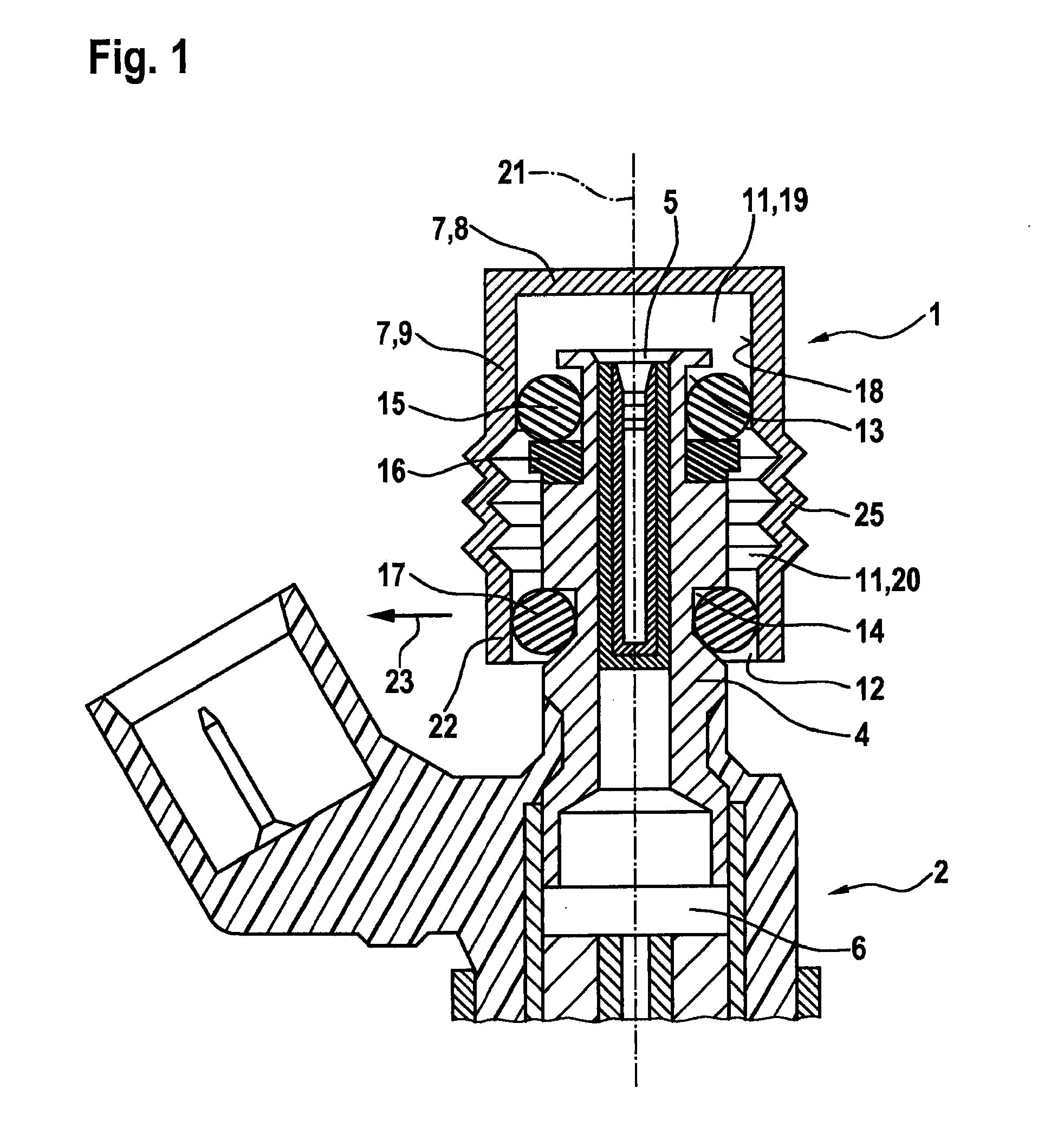
[0027]FIG. 1 shows a connecting element 1 and a fuel injector 2 of a fuel injection system 3 (FIG. 5) in a partial schematic sectional illustration corresponding to a first exemplary embodiment. Fuel injection system 3 may be used in particular for high-pressure injection in internal combustion engines. In particular, fuel injection system 3 may be used in mixture-compressing, spark ignition internal combustion engines. Connecting element 1 is particularly suited for such fuel injection systems 3.

[0028]Fuel injector 2 of fuel injection system 3 includes a fuel connector 4. During operation, fuel is guided into a fuel chamber 6 of fuel injector 2 at an inlet-side end 5 of fuel connector 4.

[0029]Connecting element 1 includes a base body 7 which has an upper part 8 and a tubular part 9. A suitable inflow bore 10 (FIG. 5) for guiding fuel into...


PUM


Abstract

A connecting element for connecting a fuel injector of a fuel injection system to a fuel-guiding component includes a base body in which a receiving chamber for a fuel connector of the fuel injector is provided. The fuel connector, which is situated at least partially in the receiving chamber, is supported at least indirectly on the base body. The fuel connector is elastically supported on the base body in a radial direction.

Description

BACKGROUND OF THE INVENTION[0001]1. Field of the Invention[0002]The present invention relates to a connecting element for fuel injection systems for connecting a fuel injector to a fuel-guiding component, and a fuel injection system which includes such a connecting element. In particular, the present invention relates to the field of fuel injection systems for mixture-compressing, spark ignition internal combustion engines.[0003]2. Description of the Related Art[0004]A fuel injection device is known from published German patent application document DE 10 2005 020 380 A1 which is characterized by a sound-decoupling design. The known fuel injection device includes a fuel injector, a receiving borehole for the fuel injector in a cylinder head of an internal combustion engine, and a fuel distributor line which includes a connecting piece. The fuel injector is introduced into the connecting piece with a partial overlap. In one possible embodiment, a slotted snap ring is provided which en...

Claims


Application Information

Patent Timeline
IPC IPC(8): F02M55/00F02M61/16F16L27/107F02M55/02
CPCF02M55/004F16L27/107F02M61/167F02M55/02F02M61/14F02M69/462F02M2200/856F02M2200/09F02M2200/9015F02M2200/16
Inventor REINHARDT, WILHELMSCHEEF, VOLKERMAYER, MICHAELREHWALD, ANDREASHERMANN, JANROGLER, PHILIPPGLASER, ANDREASHORST, HANS-GEORGRIEMER, MARTINKNORPP, MICHAELFISCHER, MICHAEL
Owner ROBERT BOSCH GMBH
Why Eureka
Try Eureka