
LED lighting apparatus

a technology of led lighting and lighting components, which is applied in the direction of lighting and heating equipment, lighting support devices, semiconductor devices for light sources, etc., can solve the problems of reduced illumination, electrical circuit failure, and expensive apparatus structure configuration

Active Publication Date: 2015-12-03
SAMJIN LND
View PDF10 Cites 4 Cited by
  • Summary
  • Abstract
  • Description
  • Claims
  • Application Information

AI Technical Summary

Benefits of technology

The LED lighting apparatus described in this patent has a closed structure that is waterproof, dust-proof, and bug-proof. It also has an economical and simple internal structure that allows for efficient changes in light distribution angle. The shape of the inner frame coupled to the seal cover can be varied to provide various light distribution angles while maintaining the closed and sealed structure. Overall, this LED lighting apparatus provides efficient and effective protection against water, dust, and insects while also allowing for flexibility in lighting options.

Problems solved by technology

On the other hand, the LED lighting apparatus is penetrated by foreign matter such as dust and insects through a gap when using the device for a long period of time, and the foreign matter builds up inside the device such that the emission of light is shielded, thereby causing a reduction in illumination, and an electrical circuit failure may be generated by the foreign matter penetrated therein.
Also, in a case of outdoor use, a waterproofing function of the device is required, and for the sealing structure for the waterproofing, an expensive apparatus structure must be configured, such that the structure is complex and costly.
On the other hand, the LED lighting apparatus must have a wide light distribution angle in a case of a low ceiling and must have a narrow light distribution angle to transmit the light a long distance in a case of a high ceiling, such that it is necessary to differentiate the light distribution angle depending on the installation location, and for this, a complicated mechanism for the reflection or the refraction of light must be added inside the apparatus.

Method used


Image

  • LED lighting apparatus
  • LED lighting apparatus
  • LED lighting apparatus

Examples


Embodiment Construction

[0045]The present invention will be described more fully hereinafter with reference to the accompanying drawings, in which exemplary embodiments of the invention are shown. As those skilled in the art would realize, the described embodiments may be modified in various different ways, all without departing from the spirit or scope of the present invention. The drawings and description are to be regarded as illustrative in nature and not restrictive. Like reference numerals designate like elements throughout the specification.

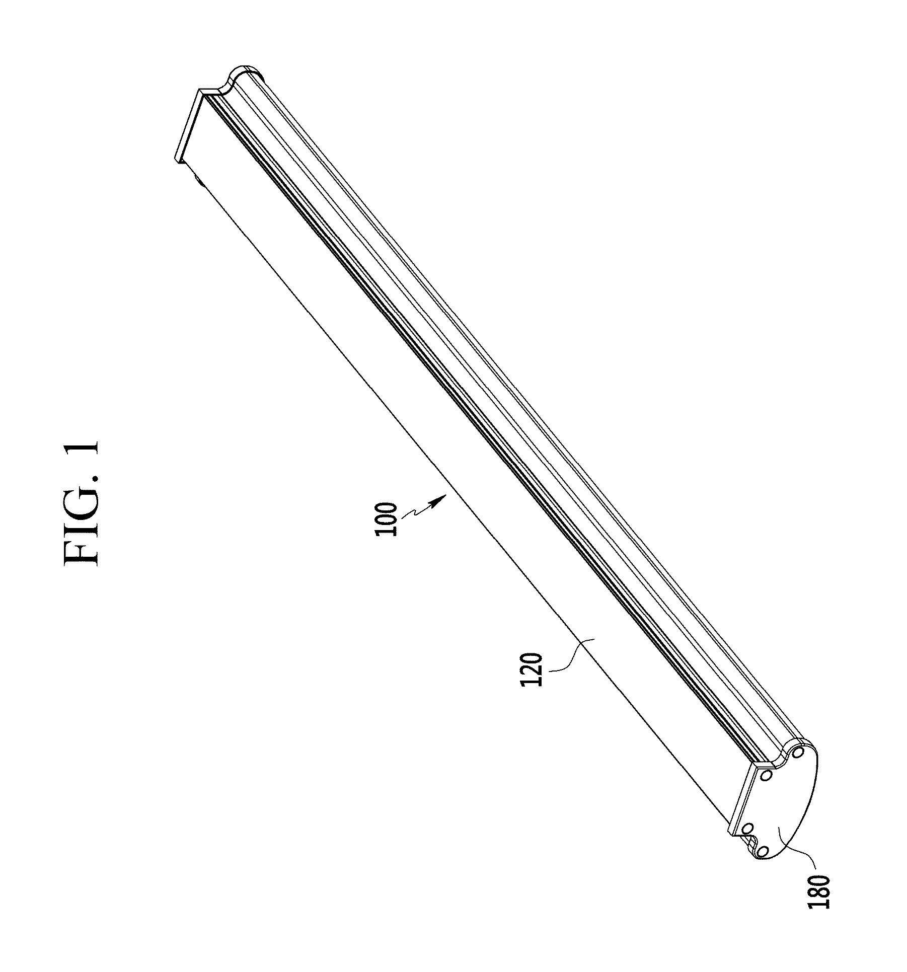
[0046]FIG. 1 is a perspective view of an LED lighting apparatus according to an exemplary embodiment of the present invention.

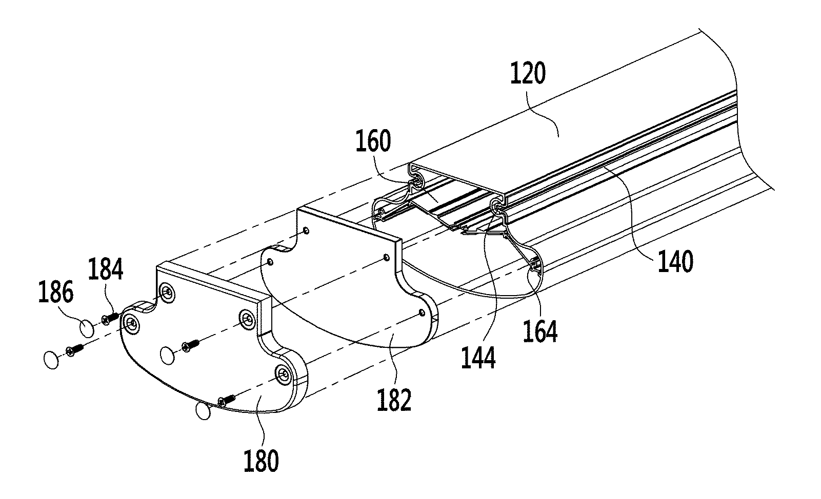
[0047]Referring to FIG. 1, the LED lighting apparatus 100 according to an exemplary embodiment of the present invention is formed as a longitudinal type like the fluorescent lamp, and may include a main cover 120 and a close-and-seal cover 180 closing and sealing both ends of a length direction of the main cover 120.

[0048]That is, in the L...


PUM


Abstract

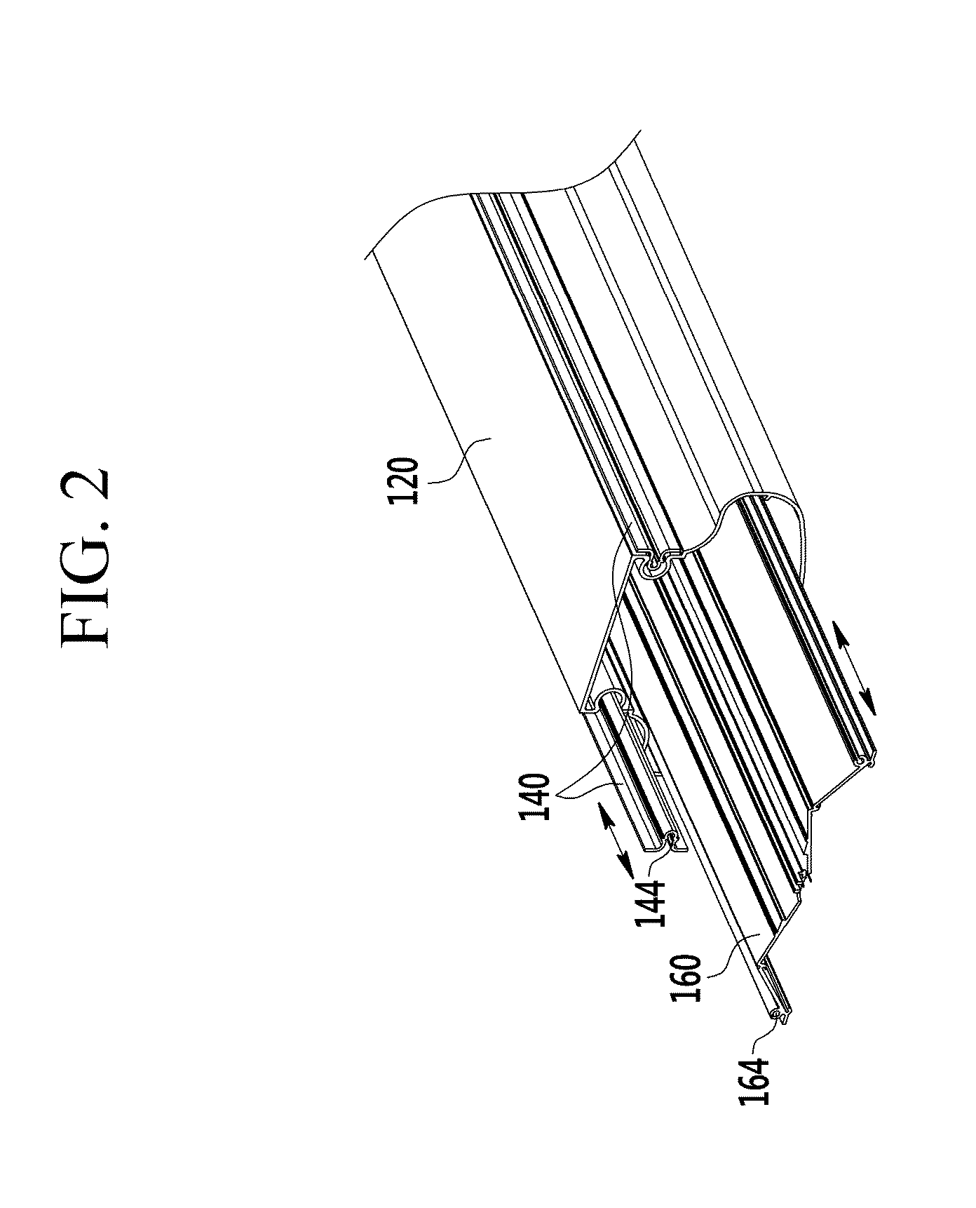
An LED lighting apparatus is disclosed. The lighting apparatus according to an exemplary embodiment of the present invention includes: a main cover with an elongated pipe shape having a cross-section formed of a closed curve line and both ends of a length direction formed to be open; an external frame sliding-coupled to an external surface of the main cover along a length direction of the main cover; an inner frame having a shape extending in a direction parallel to the length direction of the main cover and sliding-coupled to an internal surface of the main cover along with the length direction of the main cover to be positioned at the inner space of the main cover; and a close-and-seal cover closing and sealing both open ends of the main cover to close and seal the inner space of the main cover, wherein the bottom surface of the inner frame supports an emitted LED, and the close-and-seal cover is coupled to the external frame and the inner frame.

Description

CROSS-REFERENCE TO RELATED APPLICATION[0001]This application claims priority to and the benefit of Korean Patent Application No. 10-2014-0067248 filed in the Korean Intellectual Property Office on Jun. 2, 2014, the entire contents of which are incorporated herein by reference.BACKGROUND OF THE INVENTION[0002](a) Field of the Invention[0003]The present invention relates to an LED lighting apparatus. More particularly, the present invention relates to an LED lighting apparatus of a closed type.[0004](b) Description of the Related Art[0005]Since a light emitting diode (LED) as a light semiconductor using a compound semiconductor was invented, a white LED has been rapidly developed in an aspect of efficiency of the emitted light compared with input power.[0006]Thanks to the development of this light-efficient white LED, a characteristic that much light is emitted through low energy consumption is ensured, and currently, the white LED is replacing traditional light sources such as incand...

Claims


Application Information

Patent Timeline
Patent Type & Authority Applications(United States)
IPC IPC(8): F21V17/12F21V3/02F21V31/00F21V7/00F21V23/00F21S4/00F21V17/10
CPCF21V17/12F21S4/008F21V3/02F21Y2103/003F21V7/005F21V23/009F21V31/005F21V17/104F21V15/013F21S4/28F21Y2103/10F21Y2115/10Y10S362/80
Inventor SOHN, CHOONG-YONGPARK, GEUN KYOKIM, JONG HO
Owner SAMJIN LND
Learn More