Compact high voltage power fuse and methods of manufacture

a high-voltage power fuse and compact technology, applied in the manufacture of high-voltage, full-range power fuse fields, can solve the problems of reducing the rated ampacity, and increasing the cost of manufactur

Active Publication Date: 2015-12-03
EATON INTELLIGENT POWER LIMITED
View PDF22 Cites 25 Cited by
  • Summary
  • Abstract
  • Description
  • Claims
  • Application Information

AI Technical Summary

Problems solved by technology

This will normally have a negative effect on the fuse rating by lowering the rated ampacity due the added resistance and heat.
In another embodiment, the terminal assemblies could be different from one another on the opposing ends of the fuse housing 202 if desi...

Method used


Image

  • Compact high voltage power fuse and methods of manufacture
  • Compact high voltage power fuse and methods of manufacture
  • Compact high voltage power fuse and methods of manufacture

Examples


Embodiment Construction

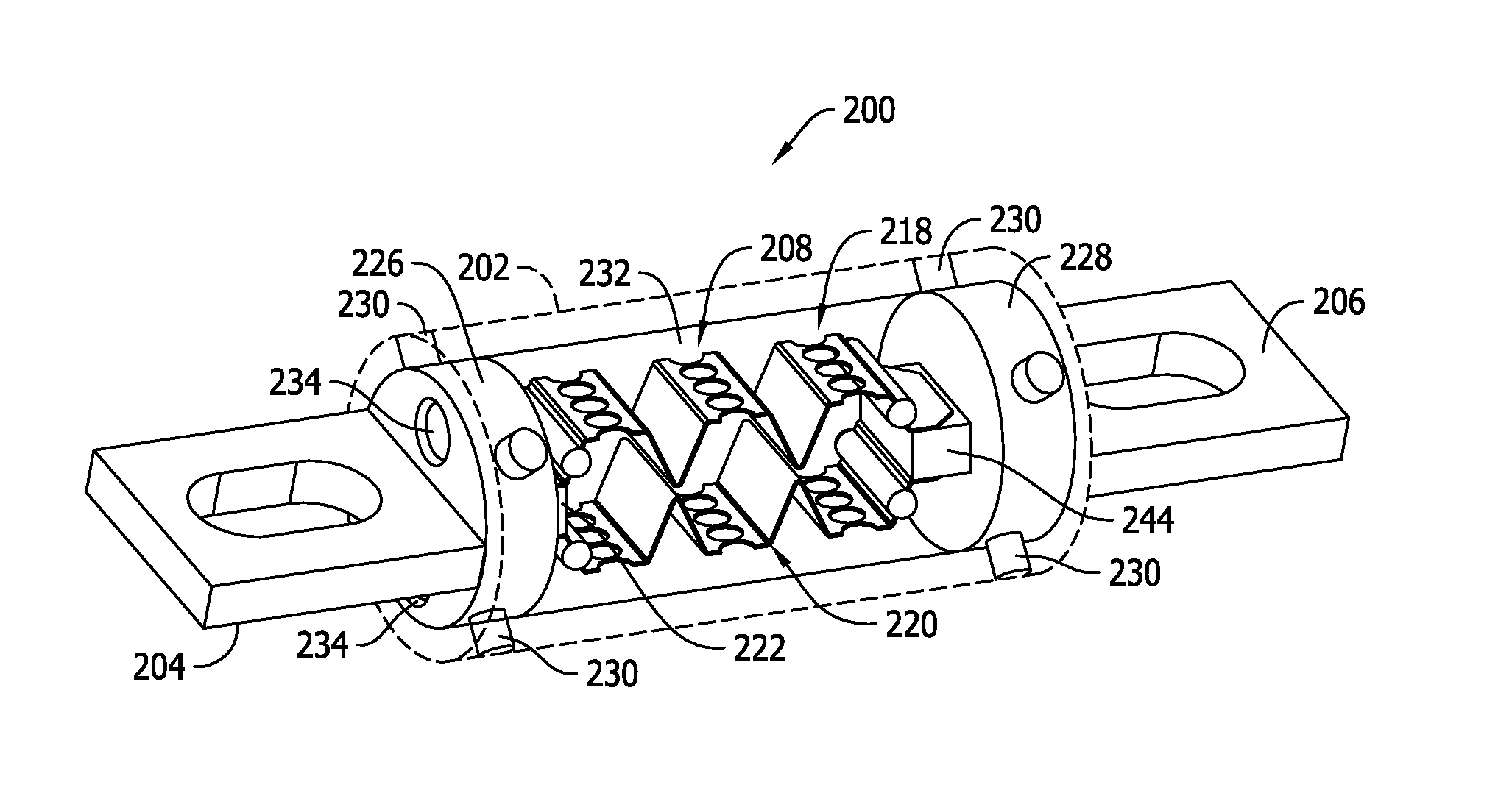
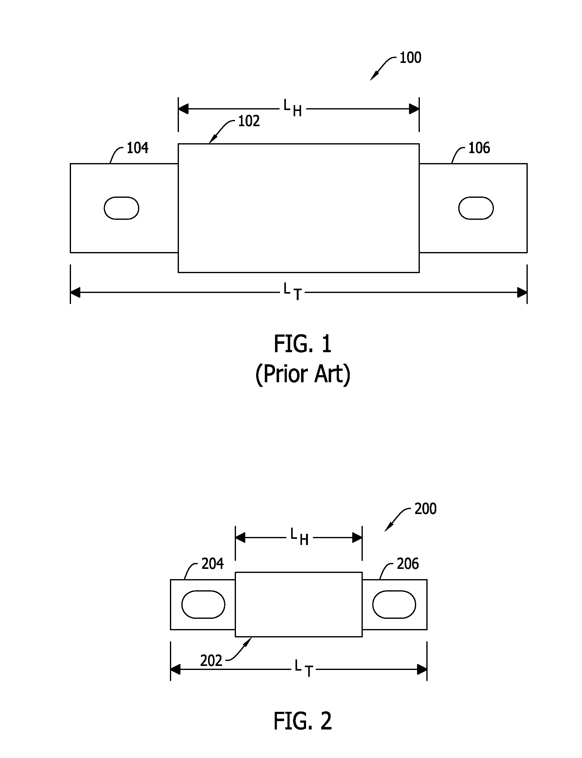
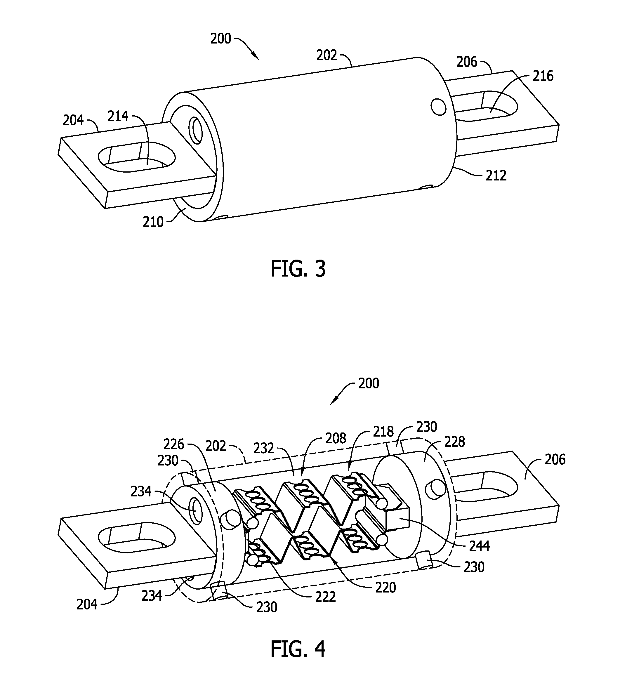
[0029]Recent advancements in electric vehicle technologies, among other things, present unique challenges to fuse manufacturers. Electric vehicle manufacturers are seeking fusible circuit protection for electrical power distribution systems operating at voltages much higher than conventional electrical power distribution systems for vehicles, while simultaneously seeking smaller fuses to meet electric vehicle specifications and demands.

[0030]Electrical power systems for conventional, internal combustion engine-powered vehicles operate at relatively low voltages, typically at or below about 48 VDC. Electrical power systems for electric-powered vehicles, referred to herein as electric vehicles (EVs), however, operate at much higher voltages. The relatively high voltage systems (e.g., 200 VDC and above) of EVs generally enables the batteries to store more energy from a power source and provide more energy to an electric motor of the vehicle with lower losses (e.g., heat loss) than conv...


PUM

PropertyMeasurementUnit
Lengthaaaaaaaaaa
Lengthaaaaaaaaaa
Currentaaaaaaaaaa

Abstract

A high voltage power fuse having a dramatically reduced size facilitated by silicated filler material, a formed fuse element geometry, arc barrier materials and single piece terminal fabrications. Methods of manufacture are also disclosed.

Description

CROSS REFERENCE TO RELATED APPLICATIONS[0001]This application is a continuation-in-part application of U.S. application Ser. No. 14 / 289,032 filed May 28, 2014, the complete disclosure of which is hereby incorporated by reference in its entirety.BACKGROUND OF THE INVENTION[0002]The field of the invention relates generally to electrical circuit protection fuses and methods of manufacture, and more specifically to the manufacture of high voltage, full-range power fuses.[0003]Fuses are widely used as overcurrent protection devices to prevent costly damage to electrical circuits. Fuse terminals typically form an electrical connection between an electrical power source or power supply and an electrical component or a combination of components arranged in an electrical circuit. One or more fusible links or elements, or a fuse element assembly, is connected between the fuse terminals, so that when electrical current flow through the fuse exceeds a predetermined limit, the fusible elements m...

Claims


Application Information

Patent Timeline
IPC IPC(8): H01H85/055H01H69/02H01H85/045
CPCH01H85/055H01H85/0456Y10T29/49108H01H2239/044H01H69/02H01H85/10H01H85/11H01H85/18H01H85/143H01H85/12H01H85/175H01H85/203
Inventor DOUGLASS, ROBERT STEPHENFINK, JOHN MICHAEL
Owner EATON INTELLIGENT POWER LIMITED
Why Eureka
Try Eureka