

Light emitting device
- Summary
- Abstract
- Description
- Claims
- Application Information
AI Technical Summary
Benefits of technology
Problems solved by technology
Method used
Image

Examples
embodiment 1
ng Device 100
[0026]As shown in FIG. 3, a light emitting device 100 includes a first light emitting element 21, a second light emitting element 22, a plurality of leads for individually driving the first light emitting element 21 and the second light emitting element 22, and a resin molding 31 that is molded integrally with the plurality of leads and is substantially rectangular in top view. The leads provided to the light emitting device 100 include a first lead 11 that is connected by wire to the first light emitting element 21, a second lead 12 that is connected by wire to the second light emitting element 22, and a third lead 13 on which the first light emitting element 21 and the second light emitting element 22 are mounted. The first lead 11 is disposed near a first corner of the resin molding 31 in top view, has a first exposed part 51 that is exposed from one of the two side surfaces that share the first corner, and is embedded in the resin molding 31 on the other side surfac...
embodiment 2
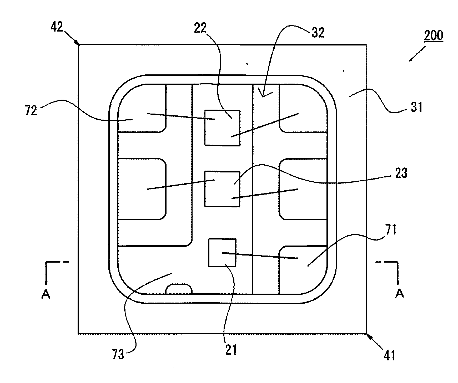
ng Device 200
[0075]As shown in FIGS. 6 to 10, a light emitting device 200 is such that a first exposed part and a second exposed part are disposed on the same side surface as the one having the third exposed part, out of the side surfaces of the resin molding. Also, the light emitting device 200 includes two third exposed parts, and one of the third exposed parts is disposed near a corner, rather than in the approximate center of the resin molding side surface.
[0076]The light emitting device 200 differs from the light emitting device 100 in that there are fewer extensions linked to the suspension pins than in the light emitting device 100, and there is no fourth exposed part. Furthermore, with the light emitting device 200, one of third exposed part is disposed near a corner of the resin molding side surfaces. That is, a third lead has extensions on both sides of an inverted L shape in top view. This arrangement of the extensions maintains the positional precision of the third lead ...
PUM
 Abstract
Description
Claims
Application Information