
Transceiver module release mechanism

a technology of transceiver module and release mechanism, which is applied in the direction of coupling device connection, optical element, instruments, etc., can solve the problems of increasing data transfer rate, increasing complexity of coupling fiber optic cable to array,

Active Publication Date: 2015-12-03
FOURTE DESIGN & DEV
View PDF0 Cites 3 Cited by
  • Summary
  • Abstract
  • Description
  • Claims
  • Application Information

AI Technical Summary

Benefits of technology

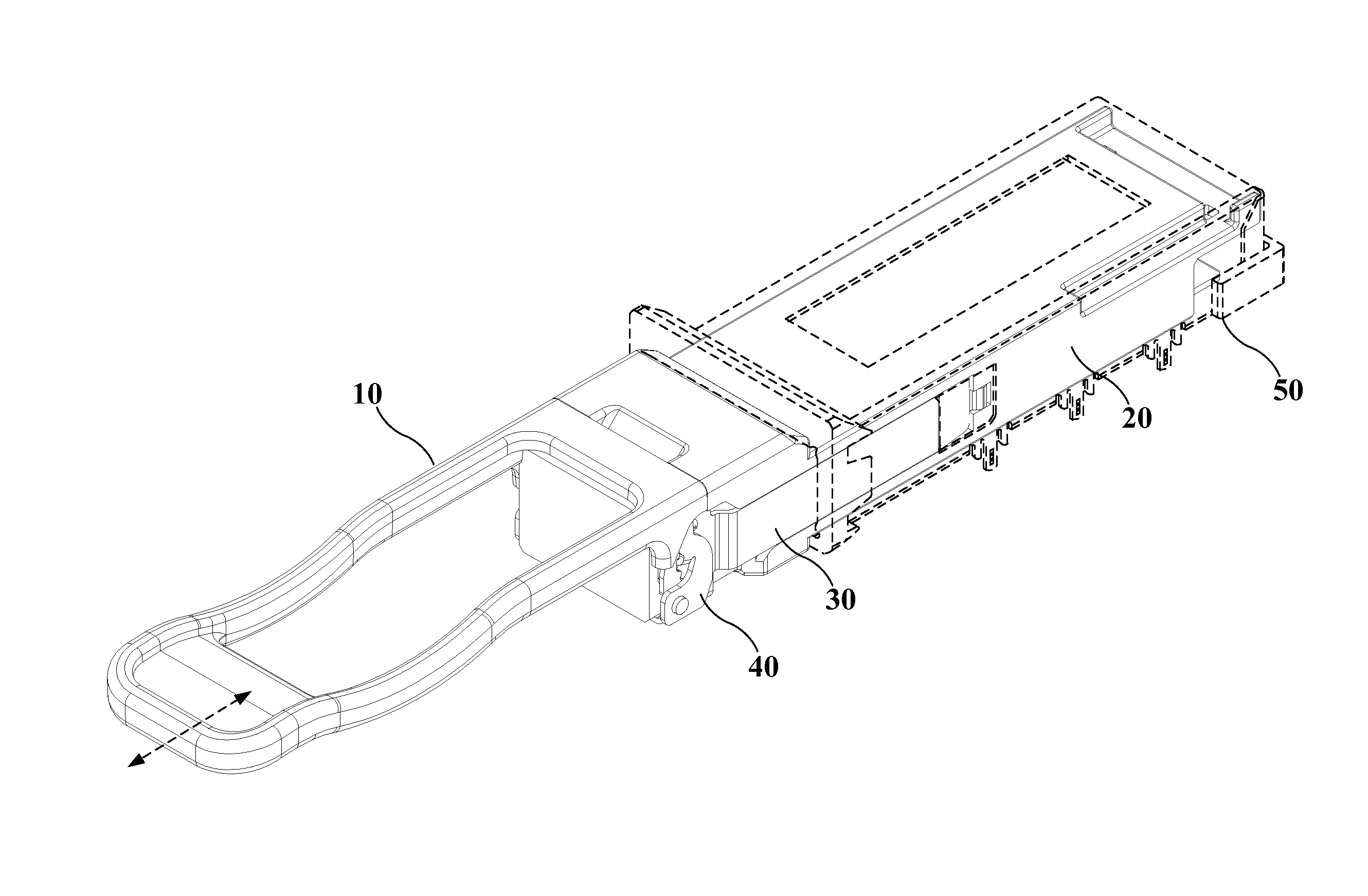
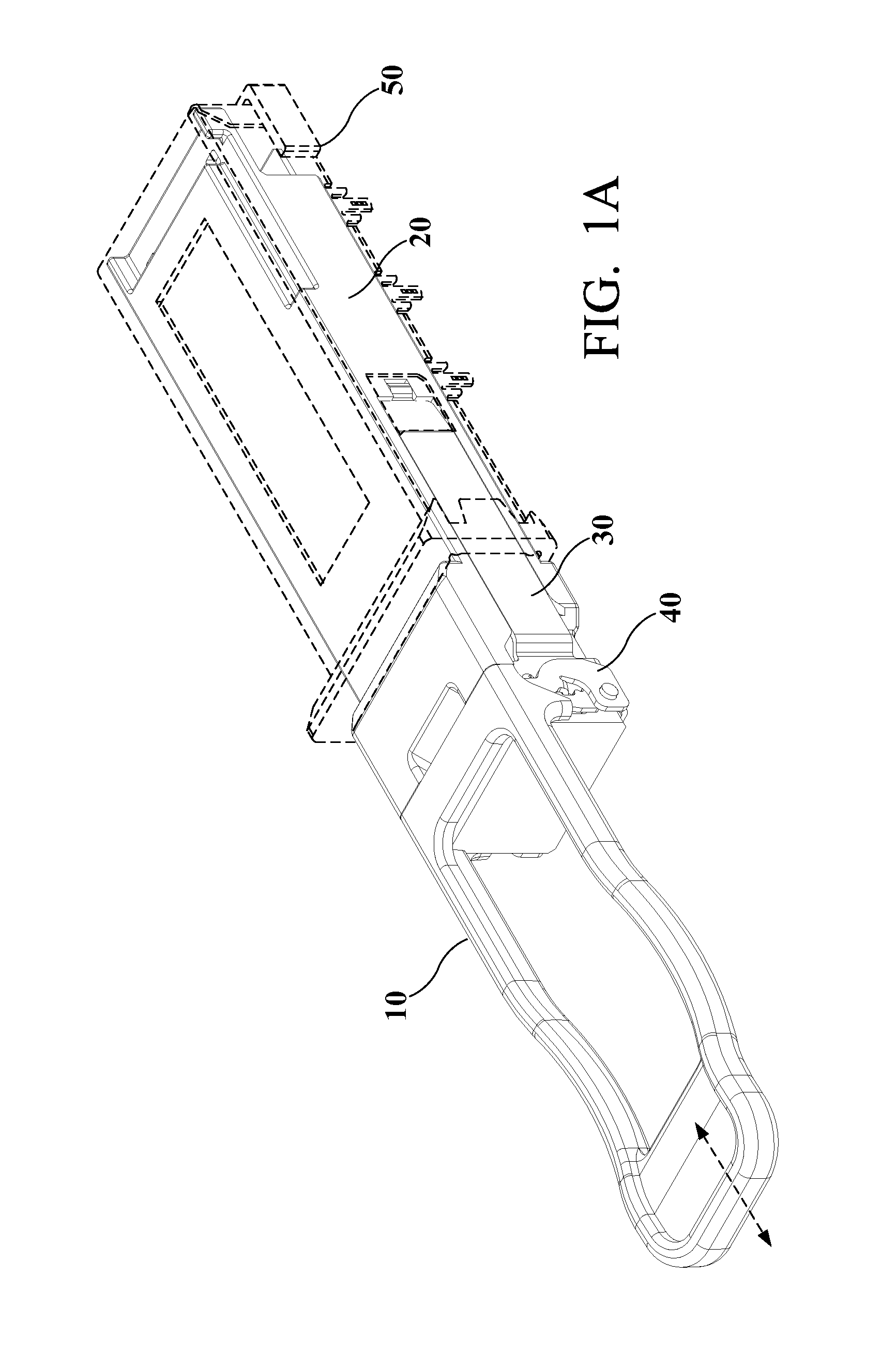
The patent text explains how a transceiver can be released from a module by using a bail and an arm assembly. The bail is closely positioned by the arm assembly and can be opened by the user through a pull tab. The bail drives the arm assembly with the transceiver module as it moves in a slot and a cam slot. The slide-block on the bail helps the bail to engage the arm assembly quickly without causing unnecessary travel of the bail or pull tab. The purpose of the invention is to make it easier and faster to release the transceiver from the module.

Problems solved by technology

Computers and related peripheral equipment, as well as satellite and communication systems in this technology age are constantly evolving and require ever increasing data transfer rates to perform highly complex tasks that drive the systems, such as digital signal processing, image analysis, and communication.
As the density of the optical arrays increases, coupling a fiber optic cable to the arrays becomes an increasingly complex task.

Method used


Image

  • Transceiver module release mechanism
  • Transceiver module release mechanism
  • Transceiver module release mechanism

Examples


Embodiment Construction

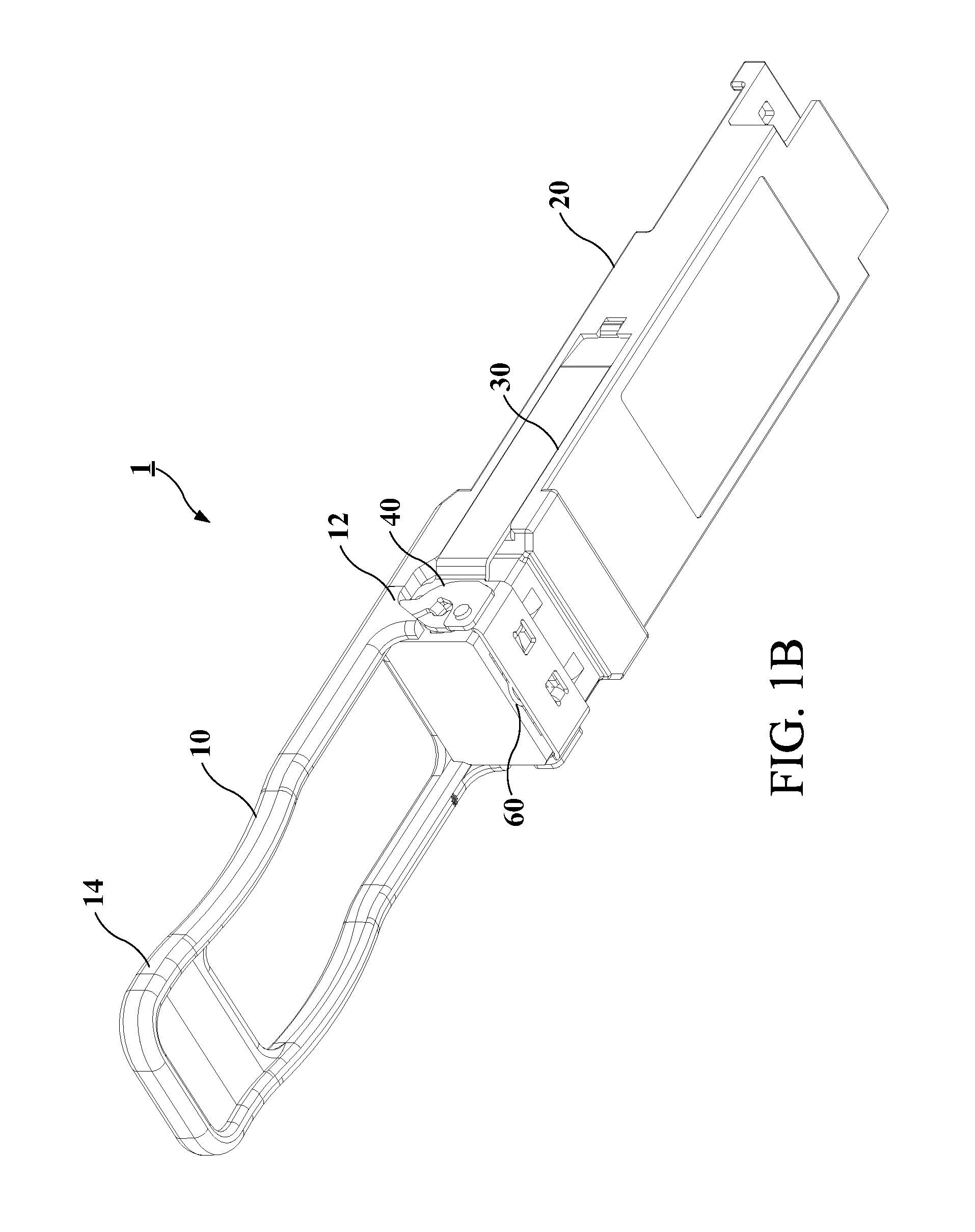
[0015]Exemplary embodiments of the present invention disclose a transceiver release system 1 as illustrated in FIGS. 1A to 1B. The release system 1 may comprises a pull tab 10, a transceiver module 20, an arm assembly 30, a bail 40, a cage 50 and a spring 60.

[0016]Each of the said elements shall be described herein. Firstly, Please refer to the FIG. 5A and FIG. 5B, it is clearly shown a the pull tab 10 having a holding portion 12 and a connecting portion 14 connected thereto, the connecting portion 14 has a hollow structure with an axis adapted to allow a hook to be rotatably connected therewith and detachably removed therefrom. However, it should be known that the pull tab 10 is not necessarily be detachable but may also be permanently attached with the bail.

[0017]Please refer to the FIGS. 2A and 2B, FIG. 2A and FIG. 2B depicts a perspective view of the combination of a transceiver module with a spring in various angles. It is clearly shown that the transceiver module 20 having a c...


PUM


Abstract

A transceiver module release system is disclosed. The system may be used to release a transceiver module housed in a cage that is permanently mounted on a printed circuit board. The release system may include a bail that rotates a slide-block through a slot to urge the bail forward in a slide-block path on the transceiver module. The bail has a hook shaped structure adapted to be connected with a detachable pull tab. As the bail begins to move forward from the locked position, wedge elements at the end of a pair of slide-block arms extending rearward from the bail may contact locking tabs on the cage, forcing the locking tabs outward. As the locking tabs are forced outward, the shoulders of the transceiver module are released, and the transceiver module is free to slide-block out of the cage as the operator pulls on the bail.

Description

FIELD OF THE INVENTION[0001]Computers and related peripheral equipment, as well as satellite and communication systems in this technology age are constantly evolving and require ever increasing data transfer rates to perform highly complex tasks that drive the systems, such as digital signal processing, image analysis, and communication. To meet current demands, optical couplers are used to transfer signals over short and long distances between computers, between two circuit boards in one computer, and even between multiple chips on a single printed circuit board. The use of high speed optical signals in place of electrical interconnections increases the achievable data transfer rate to meet with current demands.[0002]An optical transmitter / receiver (transceiver) module typically includes both light emitting devices such as vertical cavity surface emitting lasers (VCSEL's) and light detecting devices such as photodiodes. Driver / receiver circuitry modules, typically in the form of ap...

Claims


Application Information

Patent Timeline
IPC IPC(8): H01R13/629
CPCH01R13/62905G02B6/4246G02B6/4261G02B6/428
Inventor ISTA, TYLERGOLDEN, ROBERTBIANCHINI, GIONI
Owner FOURTE DESIGN & DEV
Learn More