
Method of and system for projecting digital information on a real object in a real environment

a projector and real object technology, applied in the field of projectors, can solve the problems of introducing additional error sources, and reducing the field of view of the projector

Active Publication Date: 2015-12-03
APPLE INC
View PDF13 Cites 46 Cited by
  • Summary
  • Abstract
  • Description
  • Claims
  • Application Information

AI Technical Summary

Benefits of technology

The patent describes a feature of a visible light projector that makes the projector's field of view bigger when it's close to the viewer and smaller when it's further away. This helps to improve the projector's performance and makes it easier to see what it's showing.

Problems solved by technology

For this, a calibration procedure is often performed to estimate the spatial transformation based on 2D-2D, 2D-3D, or 3D-3D correspondences which is a challenging step for building up projective AR systems.
A problem of the approach is that the position and orientation of the markers relative to the car's coordinate system has to be measured beforehand.
These two developed systems have several limitations.
Furthermore, the visual markers themselves need to be registered with the car, beforehand, which introduces additional error sources.
However, the robotic pan-tilt apparatus is expensive and the controlled movement of the camera and laser system is difficult to realize.
Also sampling the environment with the laser takes a lot of time, as only one point at a time can be sensed.
During the calibration, they require a projection on a board, which means that they cannot calibrate by projecting on any object of interest.
In order to calibrate the spatial relationship between a projector and a real object and estimate the intrinsic parameter of the projector in projective AR applications or systems, all of the previous methods require a complex procedure and / or an expensive hardware setup.
This definitely reduces the usability and efficiency of the projective AR application or systems.

Method used


Image

  • Method of and system for projecting digital information on a real object in a real environment
  • Method of and system for projecting digital information on a real object in a real environment
  • Method of and system for projecting digital information on a real object in a real environment

Examples


Embodiment Construction

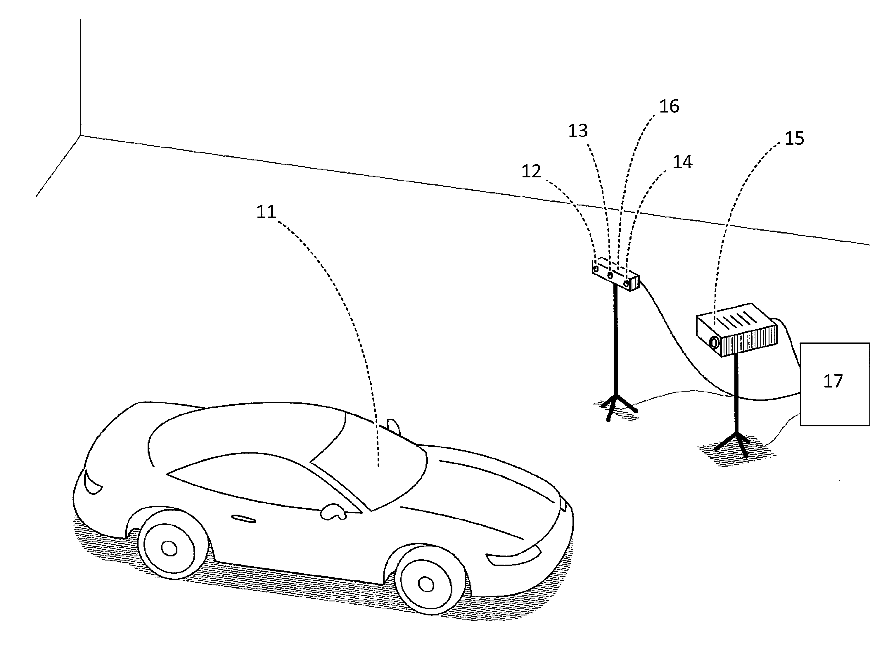
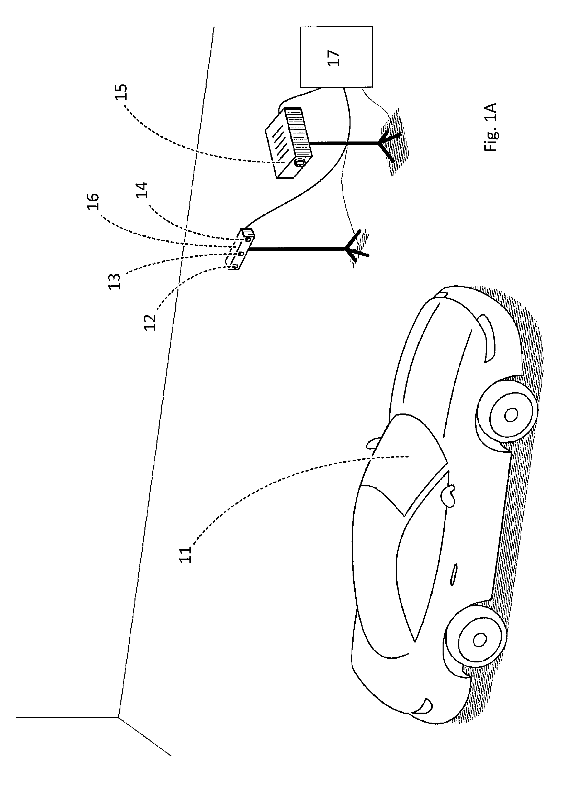
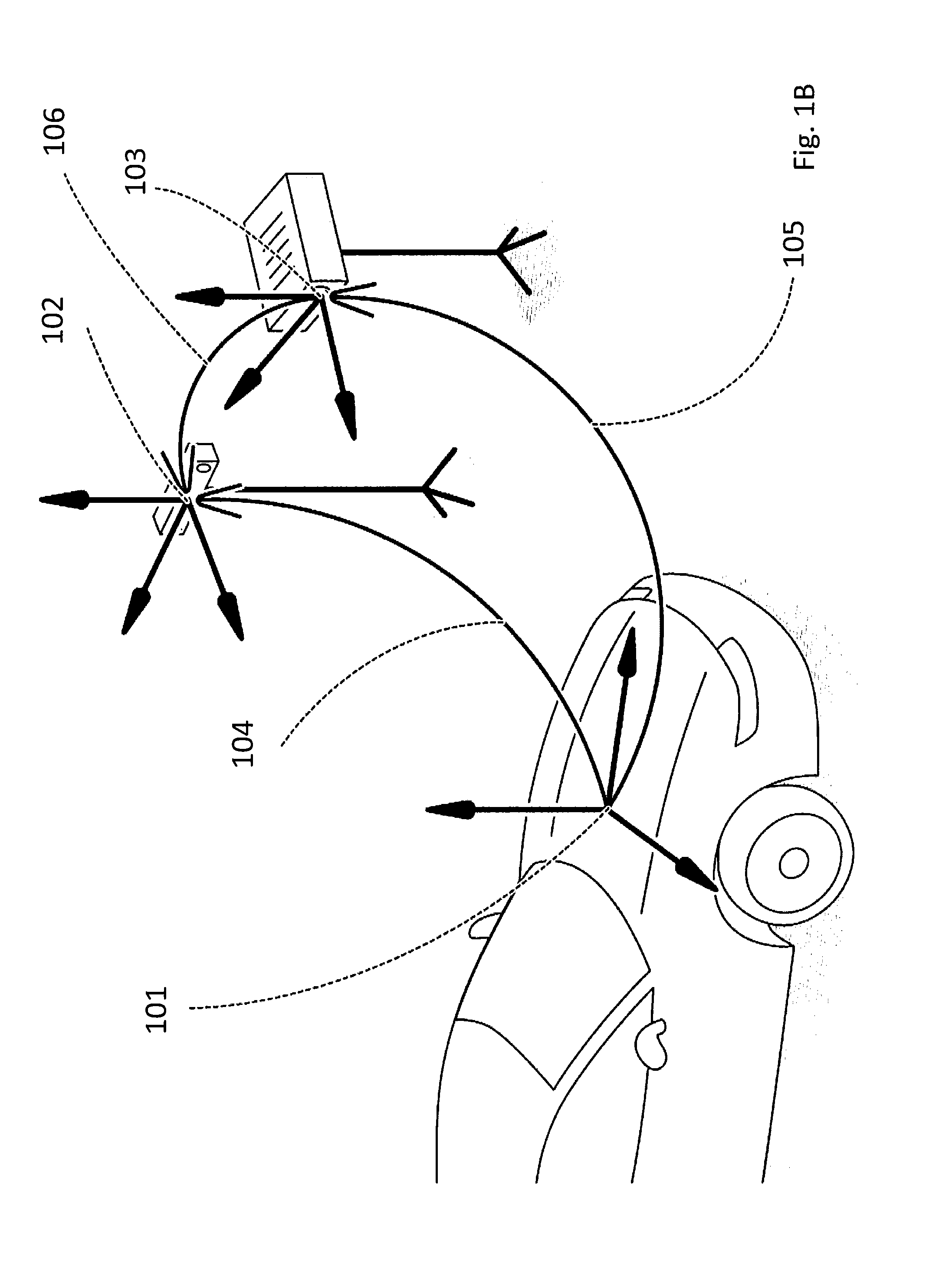
[0060]In the following description of embodiments and aspects of the invention, it is mainly referred to the system setup according to FIGS. 1A and 1B, which are only meant as exemplary system setups for explaining the invention without limiting the invention to any particular aspects shown therein. Generally, a system setup according to the invention is capable of projecting digital information on a real object in a real environment. In the present example, the real object is a car 11, however any other real object or parts thereof may also be used. The system includes a visible light projector 15 adapted for projecting digital information on a real object, such as the car 11, or part of a real object in a real environment, a camera 12 (particularly a visible light camera, such as a RGB camera or other types as set out herein below) adapted for capturing at least one image of the real object 11 with projected digital information, and a depth sensor (comprising, in the present examp...


PUM


Abstract

A method of projecting digital information on a real object in a real environment includes the steps of projecting digital information on a real object or part of a real object with a visible light projector, capturing at least one image of the real object with the projected digital information using a camera, providing a depth sensor registered with the camera, the depth sensor capturing depth data of the real object or part of the real object, and calculating a spatial transformation between the visible light projector and the real object based on the at least one image and the depth data. The invention is also concerned with a corresponding system.

Description

[0001]This application is entitled to the benefit of, and incorporates by reference essential subject matter disclosed in PCT Application No. PCT / EP2012 / 077060 filed on Dec. 28, 2012.BACKGROUND OF THE INVENTION[0002]1. Technical Field[0003]The invention is related to a method of and system for projecting digital information on a real object in a real environment. Further, the invention is related to a computer program product comprising software code sections for performing the method when running on a computer system.[0004]2. Background Information[0005]Augmented reality (AR) systems could enhance a real environment by directly visually augmenting the real environment by computer-generated digital information. For example, such digital information is virtual information for augmenting visual impressions of the real environment. Typical applications are known as, for example, so-called projector-based AR, projective AR or spatial AR, such as referred to in reference [1]. The digital...

Claims


Application Information

Patent Timeline
IPC IPC(8): H04N9/31H04N13/02H04N5/33H04N13/00H04N5/225
CPCH04N9/3185H04N13/0037H04N13/0022H04N2013/0081H04N5/332H04N9/3191H04N13/0257H04N5/2256H04N9/3194G01B11/24G01B11/25H04N13/128H04N13/15H04N13/257G06T7/80H04N23/11H04N23/56
Inventor MEIER, PETERBENHIMANE, SELIMEKURZ, DANIEL
Owner APPLE INC
Learn More