Motor vehicle with a rear diffuser

Active Publication Date: 2015-12-10
DR ING H C F PORSCHE AG
View PDF0 Cites 18 Cited by
  • Summary
  • Abstract
  • Description
  • Claims
  • Application Information

AI Technical Summary

Benefits of technology

[0010]This arrangement combined with the adjustability of the rear part of the diffuser enables a negative lift force to be controlled and can reduce the aerodynamic drag. The positive lift force is increased at the downwardly pivoted position of the rear part of the diffuser. However, the aerodynamic drag drops in relation to the operative position with the upwardly pivoted rear part of the diffuser. The pivotable rear part of the diffuser can be adjusted in a simple manner, with the required space needed being small.
[0011]The axis of rotation of the pivotable rear part of the diffuser preferably is arranged at a position approximately ⅓ of the diffuser length, and hence the pivotable rear part of the diffuser defines a length of a

Problems solved by technology

However, the aerodynamic drag drops in relation to the operativ

Method used


Image

  • Motor vehicle with a rear diffuser
  • Motor vehicle with a rear diffuser
  • Motor vehicle with a rear diffuser

Examples


Example

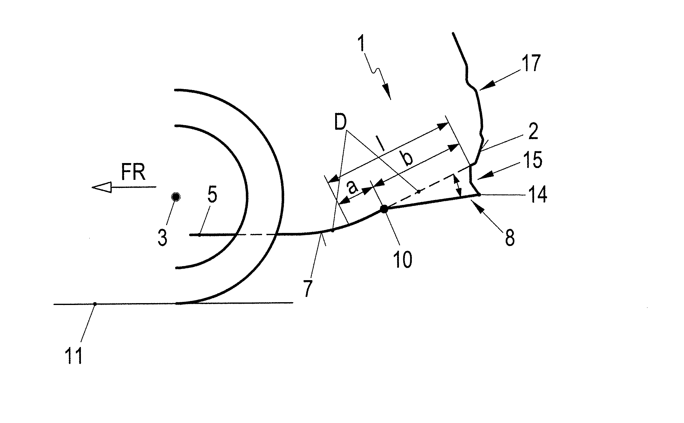
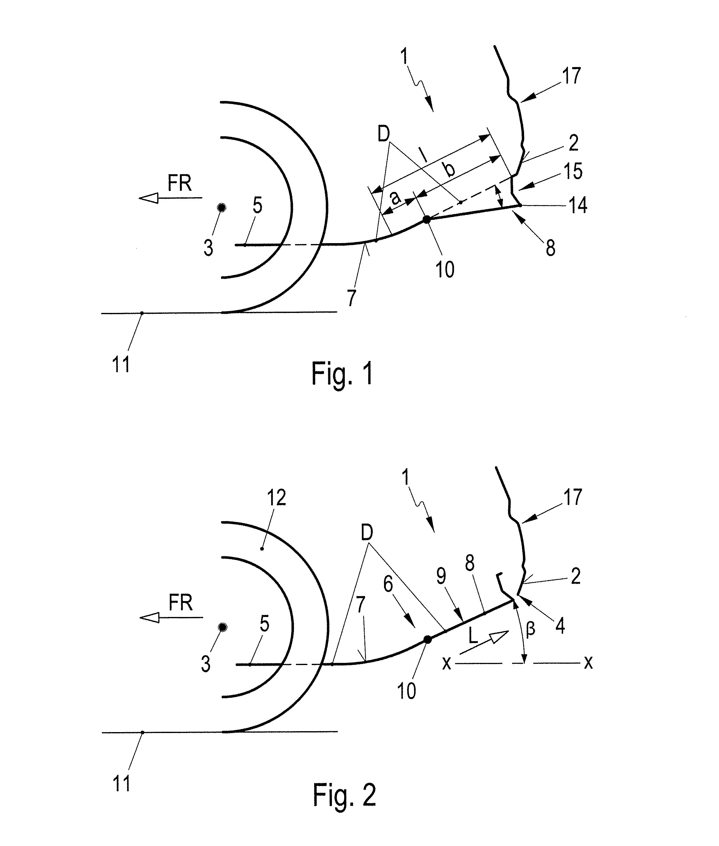
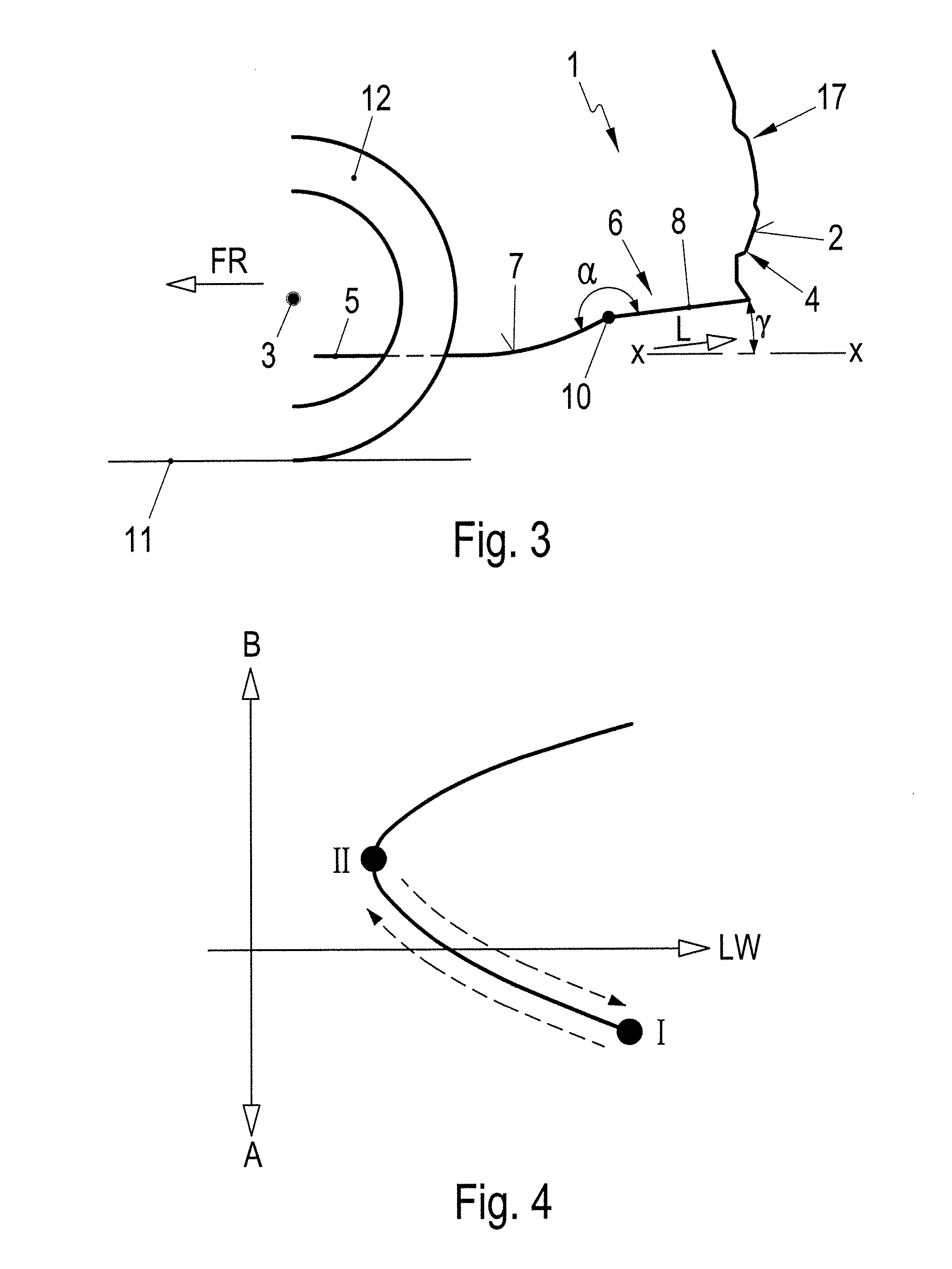
[0021]A motor vehicle 1 has a rear region 2 with a diffuser D on the underbody 5 from a rear axle 3 to a lower edge 4 of the rear region 2. The diffuser has a diffuser surface 9 that rises rearward and counter to the direction of travel FR.

[0022]The diffuser D is arranged on the end region 6 of the underbody 5 at the vehicle rear H and includes a positionally fixed front part 7 and a pivotable rear part 8 that adjoins the rear end of front part 7 of the diffuser D, as seen with respect to the direction of travel FR. The rear part 8 of the diffuser D has the diffuser surface 9 that rises in an upwardly folded operative position I. However, the rear part 8 of the diffuser is pivotable via a transversely running, positionally fixed axis of rotation 10, from the upwardly pivoted operative position I down toward the ground contact area of the vehicle 11 into at least one lower, unfolded operative position II. In the position II, the diffuser end part 8 is at a reflex angle a with respect...


PUM


Abstract

A diffuser is arranged at the rear of a vehicle in the region of the underbody and has a fixed front part and an adjoining, pivotable rear part. Negative and positive lift effects and aerodynamic drag effects are obtained by adjusting pivotable rear part between an upwardly pivoted position and a downwardly pivoted position.

Description

CROSS REFERENCE TO RELATED APPLICATION[0001]This application claims priority under 35 USC 119 to German Patent Appl. No. 10 2013 105 842.6 filed on Jun. 6, 2013, the entire disclosure of which is incorporated herein by reference.BACKGROUND[0002]1. Field of the Invention[0003]The invention relates to a motor vehicle with a rear diffuser.[0004]2. Description of the Related Art[0005]DE 11 2006 000 902 T5 discloses an aerodynamic element on the lower side of a vehicle body in the region of a rear of a vehicle. The angle of the aerodynamic element element can be changed with respect to a carriageway surface. Thus, the aerodynamic element exerts a force on the vehicle by means of an air flow that flows on the lower side of the vehicle.[0006]It is an object of the invention to provide a motor vehicle with a diffuser on the rear region of the vehicle wherein the diffuser can influence the driving performance of the motor vehicle with respect to a vehicle lifting effect and the aerodynamic d...

Claims


Application Information

Patent Timeline
IPC IPC(8): B62D35/02B62D35/00
CPCB62D35/007B62D35/02B62D37/02Y02T10/88Y02T10/82
Inventor WOLF, THOMAS
Owner DR ING H C F PORSCHE AG
Why Eureka
Try Eureka