Slide valve, in particular for controlling a motor vehicle automatic transmission

a technology of sliding valve and automatic transmission, which is applied in the direction of valve operating means/release devices, separation processes, and filtration separation, etc., can solve the problems of high hydraulic force, and achieve the effects of saving space and consequently costs, simple and reliable, and saving space and costs

Active Publication Date: 2015-12-10
ROBERT BOSCH GMBH
View PDF12 Cites 10 Cited by
  • Summary
  • Abstract
  • Description
  • Claims
  • Application Information

AI Technical Summary

Benefits of technology

[0013]Furthermore, it may be provided that the filter device is essentially configured as a circular disk (“screen”), which includes a radially outer annular holding section and a radially inner filter section. This makes it possible to save space and consequently costs. Furthermore, the configuration of the filter device differentiated in this manner makes pressing into the connector sleeve simple and reliable, as has already been explained above.
[0014]In one embodiment of the slide valve, the filter device has an annular filter section lyi

Problems solved by technology

This may cause comparatively high hydraulic forces, which act on the pressure control valve via O-

Method used


Image

  • Slide valve, in particular for controlling a motor vehicle automatic
transmission
  • Slide valve, in particular for controlling a motor vehicle automatic
transmission
  • Slide valve, in particular for controlling a motor vehicle automatic
transmission

Examples


Embodiment Construction

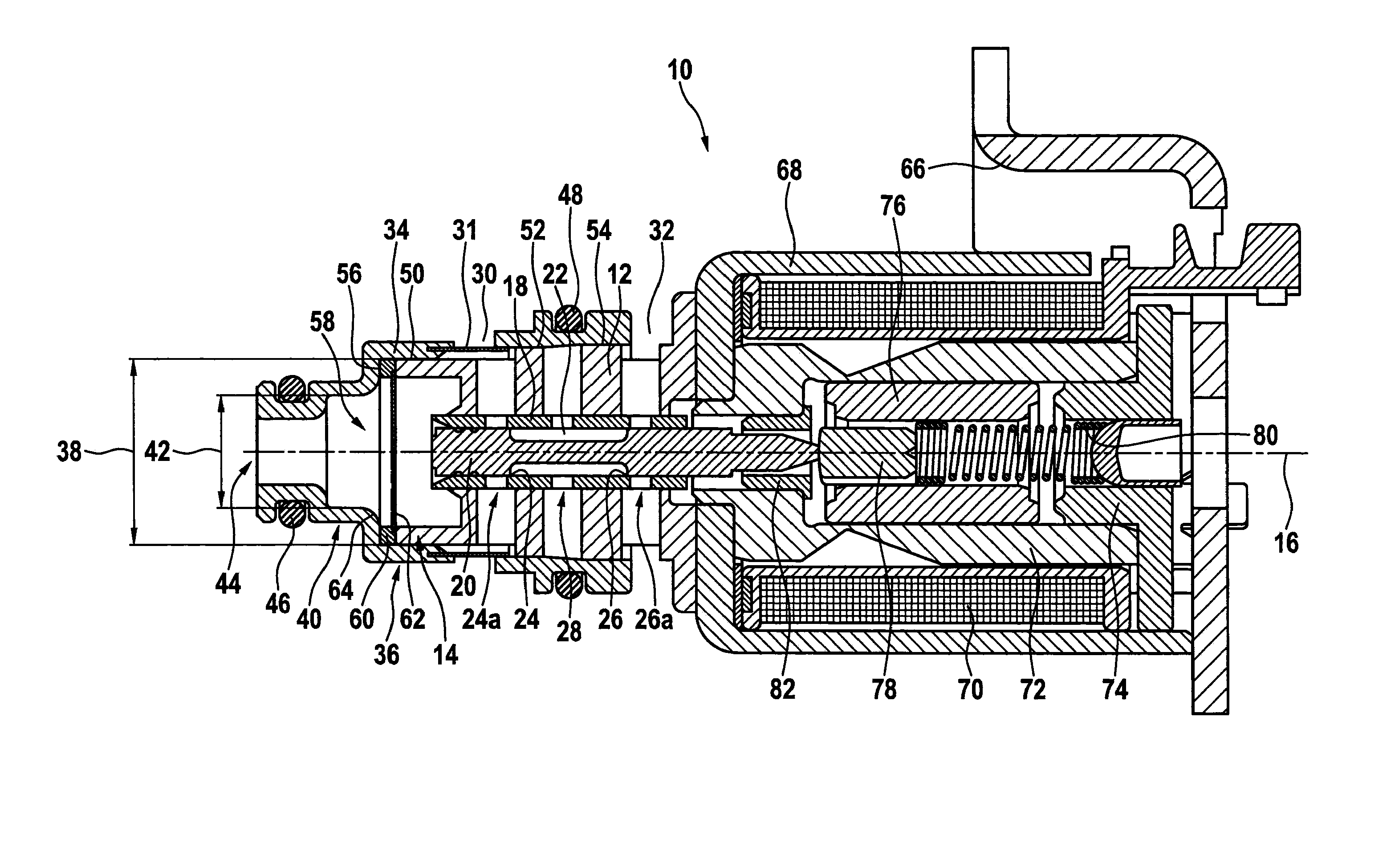
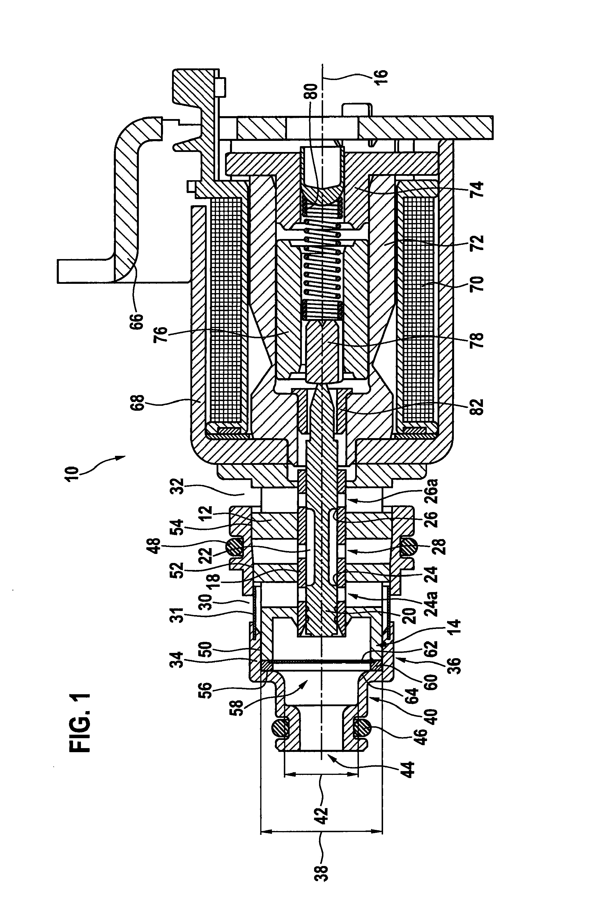
[0019]FIG. 1 shows a longitudinal section through a slide valve 10, which in the present case may be used for controlling a motor vehicle automatic transmission. Slide valve 10 includes a generally stepped cylindrical housing 12 which has an axial end section 14 in a left area in the drawing. Housing 12 and axial end section 14 are essentially configured to be rotationally symmetrical to a longitudinal axis 16. A sliding sleeve 18 is situated centrally along longitudinal axis 16 radially within housing 12 and axial end section 14, and a valve slide 20 is situated centrally along longitudinal axis 16 radially within sliding sleeve 18. Sliding sleeve 18 may be extrusion-coated by a plastic material of housing 12.

[0020]Valve slide 20 has a circumferential recess 22 extending axially radially outside in an approximately axially central area. On axial end sections of recess 22, radially circumferential control edges 24 and 26 are configured on valve slide 20, the control edges interactin...


PUM

PropertyMeasurementUnit
Diameteraaaaaaaaaa
Shapeaaaaaaaaaa
Areaaaaaaaaaaa

Abstract

A slide valve, in particular for controlling a motor vehicle automatic transmission, has a housing which includes an axial end section. A connector sleeve is situated on the axial end section of the housing, the connector sleeve having a larger diameter in a first axial area adjacent to the housing and a smaller diameter in a second axial area remote from the housing, a filter device being situated in the first axial area. The second axial area includes a hydraulic connection.

Description

RELATED APPLICATION INFORMATION[0001]The present application claims priority to and the benefit of German patent application no. 10 2014 210 530.7, which was filed in Germany on Jun. 4, 2014, the disclosure of which is incorporated herein by reference.FIELD OF THE INVENTION[0002]The present invention relates to a slide valve.BACKGROUND INFORMATION[0003]Automatic transmissions for motor vehicles in which hydraulically activatable clutches are used for shifting the gears are known from the market. For shifting operations to take place smoothly and unnoticeable to the driver, a comparatively high precision of the hydraulic components is required. For example, electromagnetically operable pressure control valves are used for this purpose. Such pressure control valves may be impaired during operation by possible dirt particles in the fluid to be controlled. For that reason, filters are often provided which are able to filter these particles from the fluid. Patent publications from this t...

Claims


Application Information

Patent Timeline
IPC IPC(8): F16K11/07B01D29/00F16H61/02B01D35/02
CPCF16K11/0708B01D35/02F16H2061/0253F16H61/0251B01D29/0095F16K31/0613
Inventor SCHUDT, KLAUSMUELLER, ERWIN
Owner ROBERT BOSCH GMBH
Why Eureka
Try Eureka