Light source module, lighting device, and lighting system

Active Publication Date: 2015-12-10
SAMSUNG ELECTRONICS CO LTD
View PDF0 Cites 11 Cited by
  • Summary
  • Abstract
  • Description
  • Claims
  • Application Information

AI Technical Summary

Benefits of technology

[0006]Exemplary embodiments provide a light source module, a lighting device, and a lighting sy

Problems solved by technology

Such lenses fabricated through such a plastic injection molding method may have a lower degree of precision than processed glass lenses.
In particular, since lens performance is determined by conditions of a microscopic injection molding process due to the trend for the slimness thereof, differences in performance may appear according to the conditions o

Method used


Image

  • Light source module, lighting device, and lighting system
  • Light source module, lighting device, and lighting system
  • Light source module, lighting device, and lighting system

Examples


Example

[0059]Hereinafter, exemplary embodiments will be described in detail with reference to the accompanying drawings.

[0060]The inventive concept may, however, be exemplified in many different forms and should not be construed as being limited to the specific exemplary embodiments set forth herein. In the drawings, the shapes and dimensions of elements may be exaggerated for clarity, and the same reference numerals will be used throughout to designate the same or like elements. Throughout this disclosure, directional terms such as “upper,”“upper (portion),”“upper surface,”“lower,”“lower (portion),”“lower surface,” or “side surface” may be used herein to describe the relationship of one element or feature to another, as illustrated in the drawings. It will be understood that such descriptions are intended to encompass different orientations in use or operation in addition to orientations depicted in the drawings.

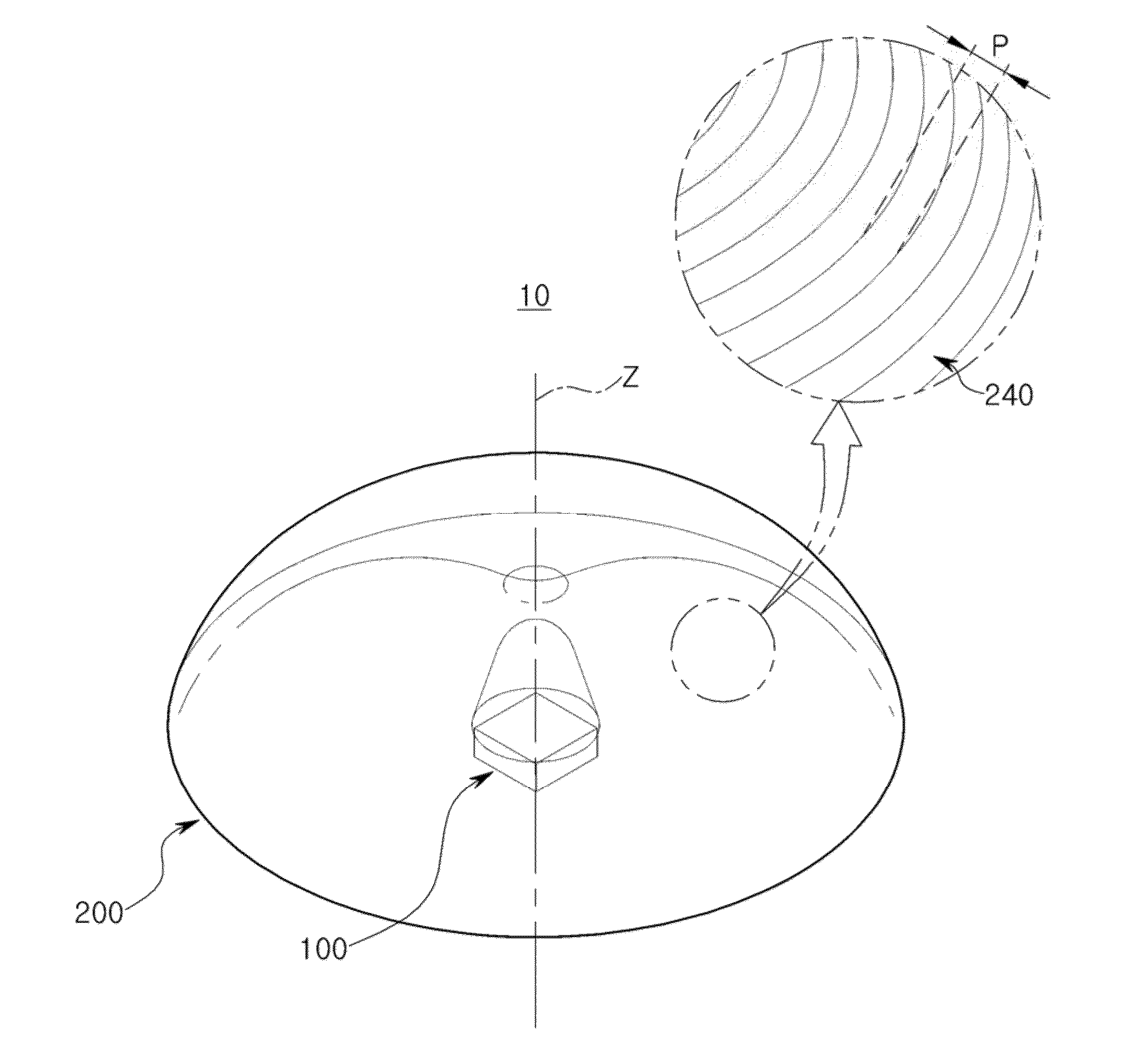
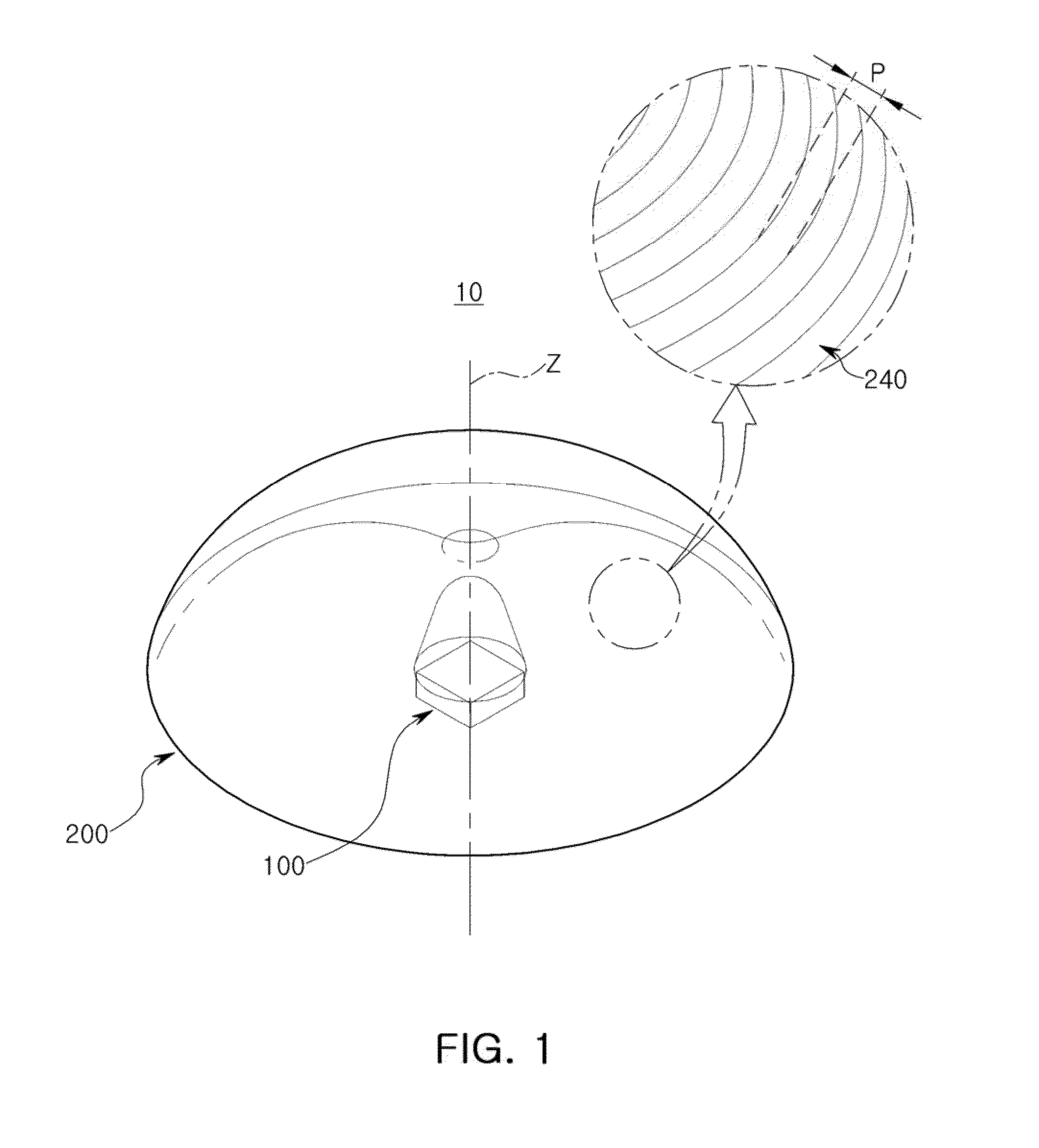
[0061]FIG. 1 is a perspective view schematically illustrating a light source ...


PUM


Abstract

A are provided a light source module. The light source module including a light emitting device configured to emit light in a light emitting direction; and an optical device including a first surface disposed over the light emitting device and having a groove recessed in the light emitting direction in a central portion through which an optical axis of the optical device passes, and a second surface disposed opposite to the first surface and configured to refract light incident through the groove to be emitted to the outside. The optical device includes a plurality of ridges disposed on the second surface and periodically arranged in a direction from the optical axis to an edge of the optical device connected to the first surface.

Description

CROSS-REFERENCE TO RELATED APPLICATION[0001]This application claims priority from Korean Patent Application No. 10-2014-0069233 filed on Jun. 9, 2014, with the Korean Intellectual Property Office, the disclosure of which is incorporated herein by reference.BACKGROUND[0002]1. Field[0003]Apparatuses and systems consistent with the present disclosure relate to a light source module, a lighting device, and a lighting system.[0004]2. Description of Related Art[0005]Commonly, lenses for light emitting diodes (LEDs) are fabricated using a plastic injection molding method in order to reduce costs. That is, a mold is fabricated with reference to an optical blueprint, and lenses are mass-produced using the mold. Such lenses fabricated through such a plastic injection molding method may have a lower degree of precision than processed glass lenses. However, recently, with an increase in demand for slimness, greater precision in the machining of lenses has been required. In particular, since len...

Claims


Application Information

Patent Timeline
IPC IPC(8): F21V13/04F21V5/04H05B33/08F21V7/00H05B44/00
CPCF21V13/04F21V7/0066F21Y2101/02H05B33/086H05B33/0872F21V5/04F21S2/005F21V7/04F21V23/003F21V5/002H01L2924/181F21Y2115/10G02B19/0066G02B3/0025G02B19/0028H05B45/20H01L2924/00012
Inventor JI, WON SOOPARK, HUN YONGHA, SANG WOO
Owner SAMSUNG ELECTRONICS CO LTD
Why Eureka
Try Eureka