Design of a heat dissipation structure for an integrated circuit (IC) chip

a technology of integrated circuits and heat dissipation structures, which is applied in the direction of cooling/ventilation/heating modifications, semiconductor/solid-state device details, semiconductor devices, etc., can solve the problems of increasing the difficulty of removing heat, the risk of overheating and boiling of coolant, and the amount of heat, so as to reduce the thermal conductivity of the adhesion layer and high thermal conductivity , the effect of high complian

Active Publication Date: 2015-12-10
ORACLE INT CORP
View PDF0 Cites 7 Cited by
  • Summary
  • Abstract
  • Description
  • Claims
  • Application Information

AI Technical Summary

Benefits of technology

The described embodiments are about a way to cool an integrated circuit (IC) die. It involves putting a layer of solder (which has high thermal conductivity) on the surface of the IC die and then attaching a heat dissipation structure to it. This structure has separate heat components that are all mechanically isolated from each other. This design makes sure that the solder layer is thin enough to reduce its thermal conductivity. The heat of the IC die is then transferred to the separate heat components, which helps to cool it.

Problems solved by technology

The dramatic increase in the power and speed of IC chips in computer systems, such as servers, has given rise to increasing challenges in removing the heat generated by these IC chips during system operation.
However, the limited chip surface area can limit the amount of heat that can be effectively removed by the coolant, and can also be subject to the risk of overheating and boiling the coolant.
Such risk subsequently limits the effective operating power of the IC chip.

Method used


Image

  • Design of a heat dissipation structure for an integrated circuit (IC) chip
  • Design of a heat dissipation structure for an integrated circuit (IC) chip
  • Design of a heat dissipation structure for an integrated circuit (IC) chip

Examples


Embodiment Construction

[0035]The following description is presented to enable any person skilled in the art to make and use the embodiments, and is provided in the context of a particular application and its requirements. Various modifications to the disclosed embodiments will be readily apparent to those skilled in the art, and the general principles defined herein may be applied to other embodiments and applications without departing from the spirit and scope of the present disclosure. Thus, the present invention is not limited to the embodiments shown, but is to be accorded the widest scope consistent with the principles and features disclosed herein.

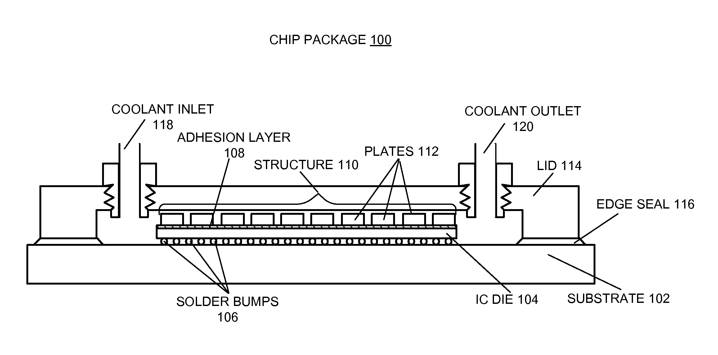
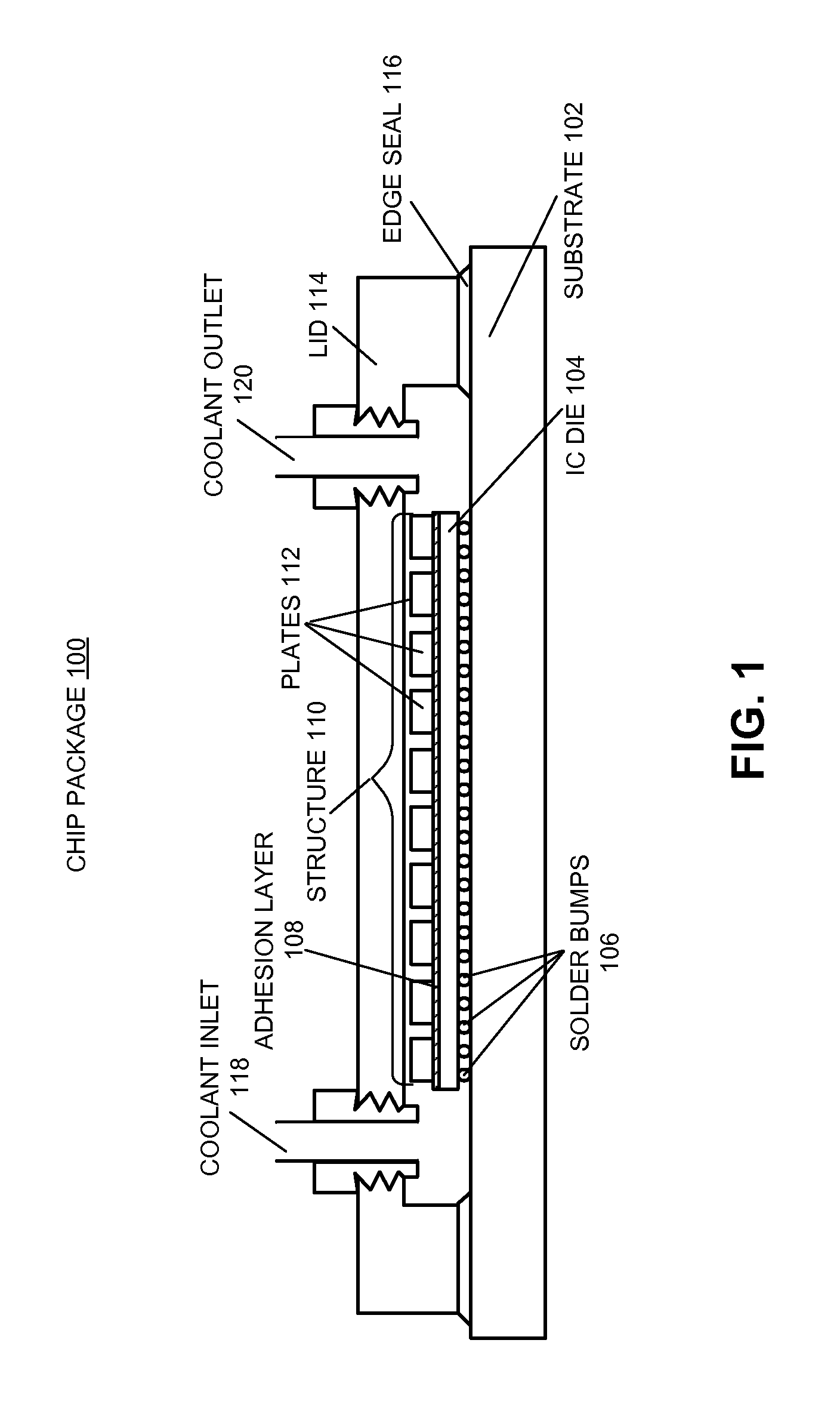
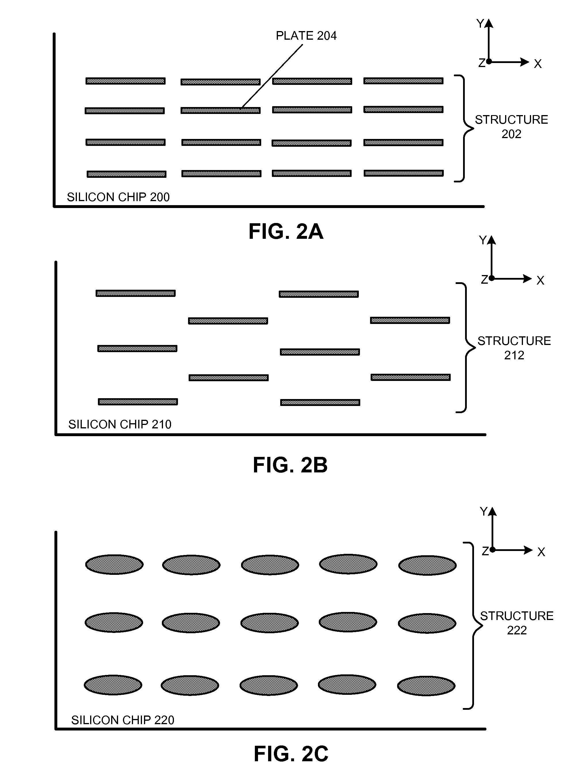
[0036]The described embodiments provide an extended heat transfer surface for IC chip heat removal, such as by using an array of fin-shaped heat dissipation plates. In some embodiments, the extended heat transfer surface is prepared separately and then attached onto the chip surface using a compliant adhesion layer made of an epoxy or a solder. Note that t...


PUM


Abstract

An apparatus for cooling an integrated circuit (IC) die is described. The apparatus includes an adhesion layer coated on a surface of the IC die, wherein the adhesion layer has high thermal conductivity. The apparatus also includes a heat dissipation structure affixed onto the adhesion layer. This heat dissipation structure further includes a set of discrete heat dissipation elements which are substantially mechanically isolated from each other. This set of discrete heat dissipation elements provides an extended heat dissipation surface for the IC die. Moreover, each of the set of discrete heat dissipation elements has high compliance, which allows the adhesion layer to be sufficiently thin, thereby reducing a thermal conductivity of the adhesion layer.

Description

RELATED CASE[0001]This application is a continuation of, and hereby claims priority under 35 U.S.C. §120 to, pending U.S. patent application Ser. No. 13 / 314,995, entitled “Design of a Heat Dissipation Structure for an Integrated Circuit (IC) Chip,” by inventors Seshasayee Ankireddi and David W. Copeland, which was filed on 8 Dec. 2011, and which is hereby incorporated by reference.BACKGROUND[0002]1. Field[0003]The disclosed embodiments are related to integrated circuit (IC) chip cooling mechanisms. More specifically, the disclosed embodiments are related to designs of a heat dissipation structure for an IC chip.[0004]2. Related Art[0005]The dramatic increase in the power and speed of IC chips in computer systems, such as servers, has given rise to increasing challenges in removing the heat generated by these IC chips during system operation. Some chip cooling techniques place an IC chip inside a lidded package which interfaces with an air-cooled heat sink for heat dissipation. Other...

Claims


Application Information

Patent Timeline
Patent Type & Authority Applications(United States)
IPC IPC(8): H01L23/367H01L23/473H01L23/498
CPCH01L23/3675H01L23/473H01L23/498H01L23/367H01L23/3672H01L23/44H01L2224/16225H01L2224/73253H05K1/0272H05K7/20927
Inventor ANKIREDDI, SESHASAYEE S.COPELAND, DAVID W.
Owner ORACLE INT CORP
Why Eureka
Try Eureka