Battery case

a battery case and battery technology, applied in the field of battery cases, can solve the problems of environmental pollution and serious energy problems, and achieve the effect of improving cooling efficiency or heating efficiency and being safe from strong external impa

Active Publication Date: 2015-12-10
EVTEC
View PDF2 Cites 30 Cited by
  • Summary
  • Abstract
  • Description
  • Claims
  • Application Information

AI Technical Summary

Benefits of technology

[0045]According to the embodiment of the present invention, the present invention provides a structure in which the cooling (heating) air is capable of cooling (heating) the front, both sides, upper surface, lower surface and rear of the battery module, thereby more improving the cooling efficiency or heating efficiency.
[0046]Also, the battery module can be securely fixed in the battery case by a lower plate and an inner upper case, etc. The battery module is wholly enclosed in a double structure by the inner upper case and outer upper case, the lower plate and lower frame, and the front frame and rear frame, so that the battery module can be safely protected from strong external impact.
[0047]Also, a heater is installed in the rear of a suction fan which sucks the air into the battery case from the outside. Accordingly, when the temperature of the battery module is reduced below an appropriate temperature, the heater is selectively operated, and then the battery module can be heated.

Problems solved by technology

The increase of a vehicle using fossil fuel like gasoline, diesel or the like causes serious energy problems due to the rapid increase of demand for the fossil fuel.
Also, the increase of the vehicle brings about not only both the environmental pollution due to excess emission of carbon dioxide and environmental problems like the increase of greenhouse gas concentrations, etc., but also various economic problems caused by rapid fluctuation in the price due to an imbalance between supply and demand, etc.

Method used


Image

  • Battery case
  • Battery case
  • Battery case

Examples


Embodiment Construction

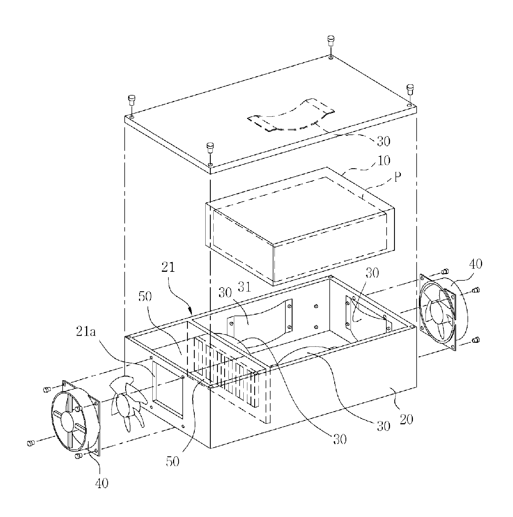
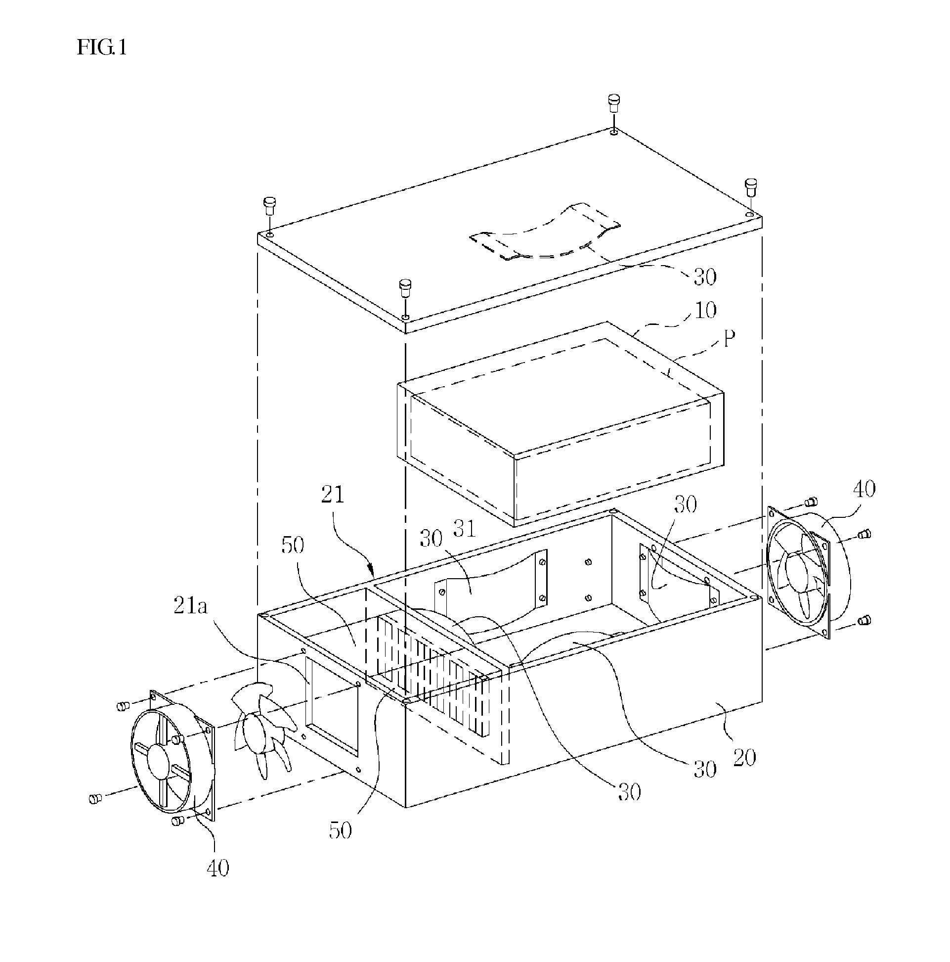
[0055]Hereafter, a battery case according to an embodiment of the present invention will be described in detail with reference to the accompanying drawings. For reference, in the following description and claims, the front and rear, and the forward and backward direction refer respectively to a surface and a direction which are located at the upstream and downstream respectively on the basis of the flow direction of the cooling (heating) air. The longitudinal direction refers to a direction along the flow direction of the cooling (heating) direction. Also, the air is divided into the cooling air and heating air according to whether the air sucked into the battery case is heated or not. The cooling (heating) air is used to commonly designate the cooling air and the heating air. This will be applied in the same manner to the following description and claims.

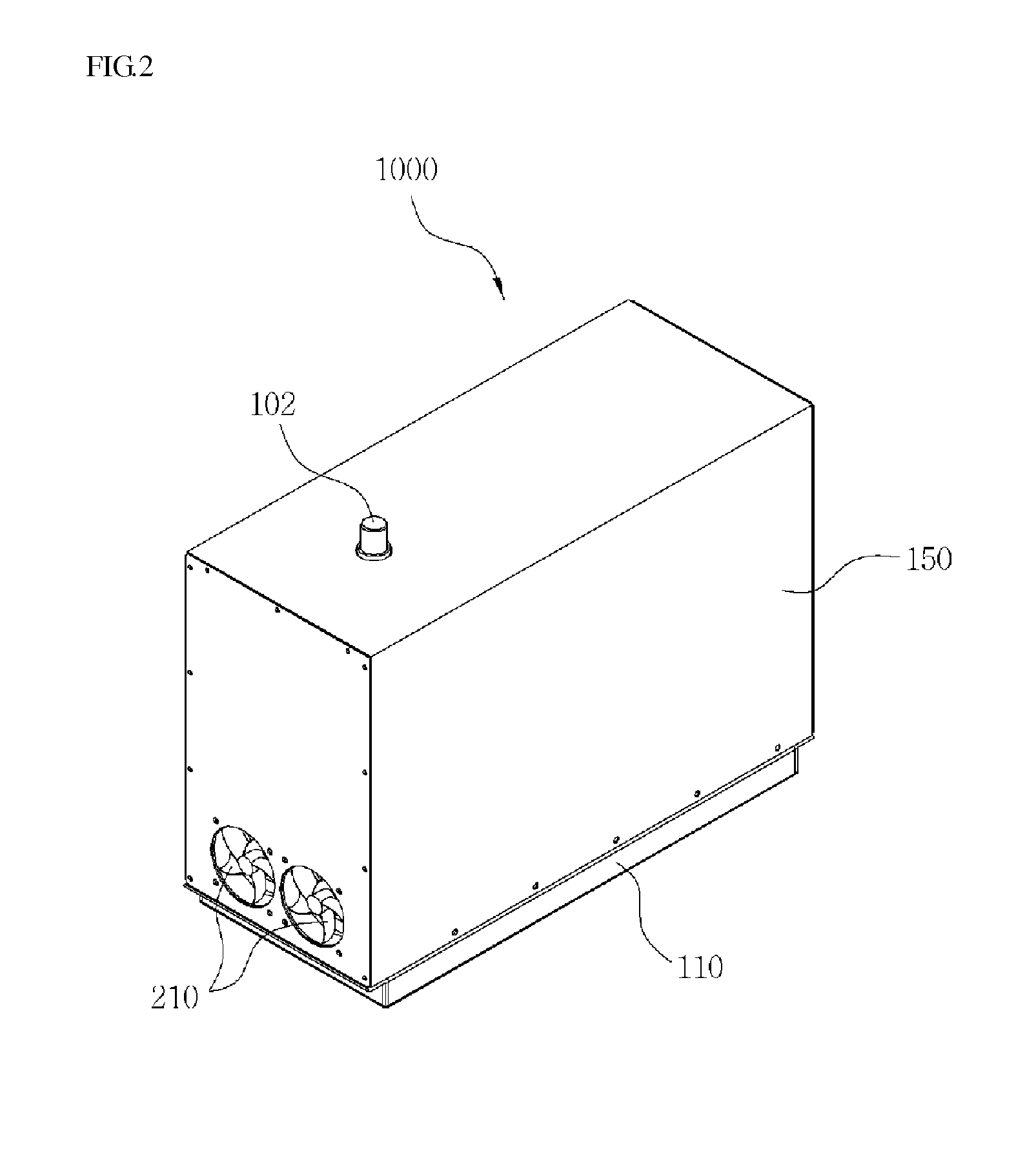
[0056]The outside of a battery case 1000 according to an embodiment of the present invention is, as show in FIG. 2, enclosed by a...


PUM

PropertyMeasurementUnit
temperatureaaaaaaaaaa
concentrationsaaaaaaaaaa
current temperatureaaaaaaaaaa

Abstract

The present invention relates to a battery case for a vehicle, and more particularly to a battery case for effectively lowering or raising the temperature of a battery module consisting of a plurality of batteries used in a vehicle or mechanical apparatus. According to the present invention, a battery case includes: a lower frame with an upper open part; a lower plate fixed to the lower frame for holding the battery module thereon, the lower plate being formed lengthwise with an inlet hole, an outlet hole, and a heat exchange hole; an inner upper frame with an upper surface having a terminal through-hole for enclosing the battery module; a front frame attached to an open front of the inner upper frame for holding a suction fan at the lower part thereof; an outer upper frame with an upper surface having a terminal through-hole for enclosing the inner upper frame and the front frame; a rear plate attached to the rear of the outer upper frame for holding an exhaust fan; and a guide partition wall arranged in the side of the inner upper frame so as to closely contact the battery module, characterized in that the guide partition wall guides the cooling (heating) air sucked by the suction fan along a zigzag path from the lower part of the side of the battery module to the upper part thereof to the exhaust fan.

Description

TECHNICAL FIELD[0001]The present invention relates to a battery case, and more particularly to a battery case capable of safely protecting a battery module from external impacts and of effectively lowering or raising the temperature of the battery module in a vehicle or mechanical apparatus, etc., which uses the battery module formed by combining in series or in parallel a plurality of batteries.BACKGROUND ART[0002]The increase of a vehicle using fossil fuel like gasoline, diesel or the like causes serious energy problems due to the rapid increase of demand for the fossil fuel. Also, the increase of the vehicle brings about not only both the environmental pollution due to excess emission of carbon dioxide and environmental problems like the increase of greenhouse gas concentrations, etc., but also various economic problems caused by rapid fluctuation in the price due to an imbalance between supply and demand, etc.[0003]To solve the problems, active technical developments are made, w...

Claims


Application Information

Patent Timeline
Patent Type & Authority Applications(United States)
IPC IPC(8): H01M2/10H01M10/6566H01M10/625H01M10/6563H01M10/613H01M10/615H01M50/103H01M50/209H01M50/262H01M50/296
CPCH01M2/1072H01M10/613H01M10/615H01M2220/20H01M10/6563H01M10/6566H01M10/625B60K1/04B60K11/06B60K2001/005Y02E60/10H01M50/262H01M50/209H01M50/296H01M50/103
Inventor SOHN, IL SEONSHON, KYU SEON
Owner EVTEC
Why Eureka
Try Eureka