
Pressure measuring catheter having reduced error from bending stresses

a technology of bending stress and pressure measurement, which is applied in the field of pressure measuring catheters, can solve the problems of difficult to isolate the pressure sensor from the bending stress experienced, incorrect pressure reading or bend error, and the general non-disagreement of clinicians for guide wires

Active Publication Date: 2015-12-17
MEDTRONIC VASCULAR INC
View PDF6 Cites 27 Cited by
  • Summary
  • Abstract
  • Description
  • Claims
  • Application Information

AI Technical Summary

Benefits of technology

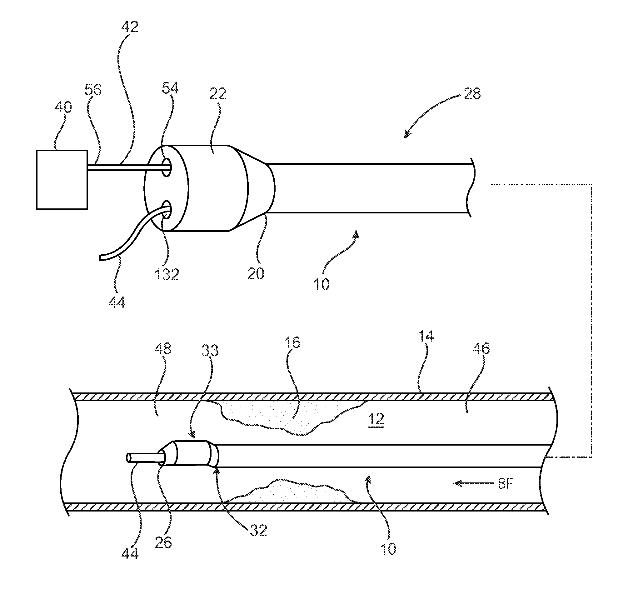
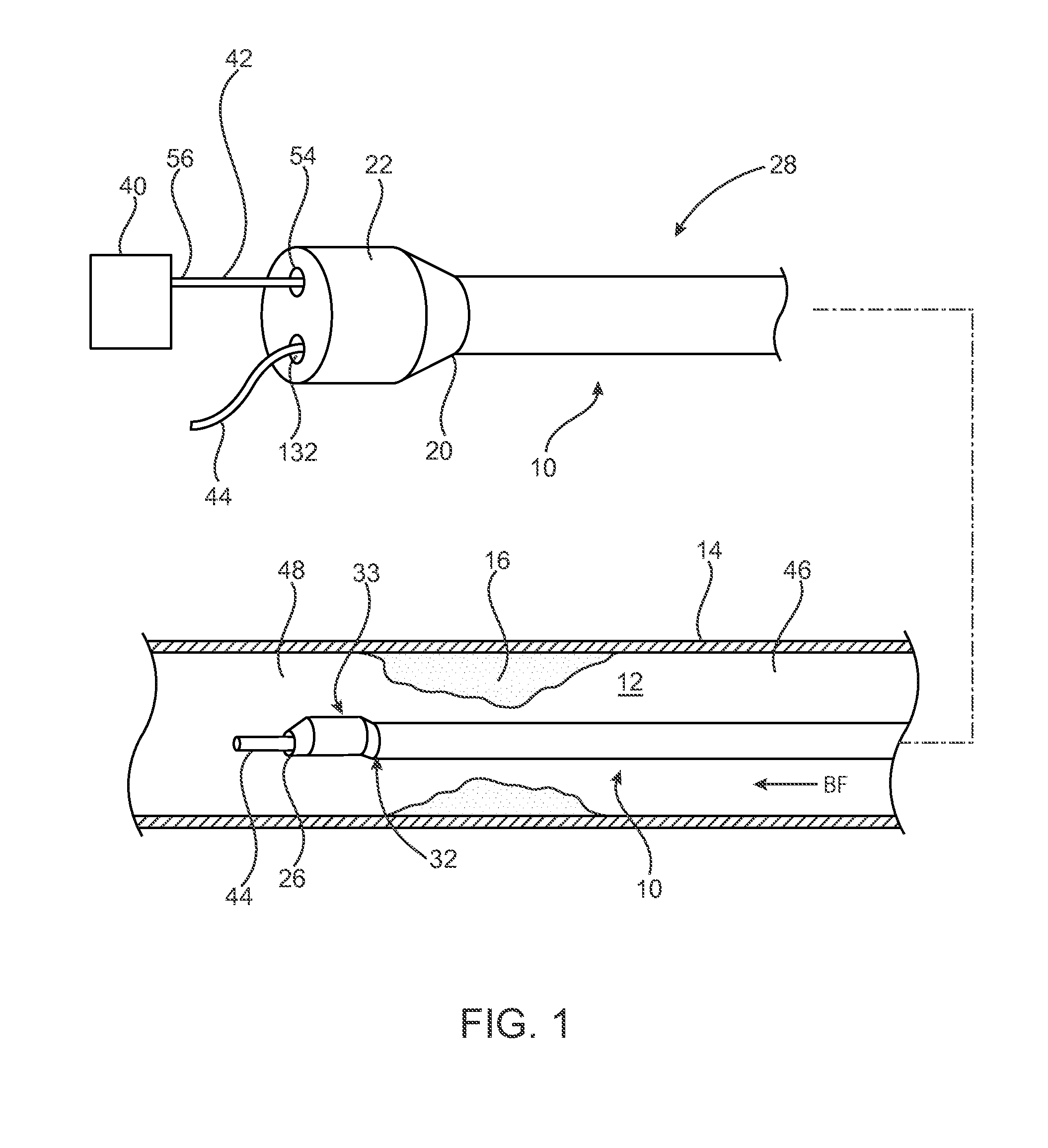
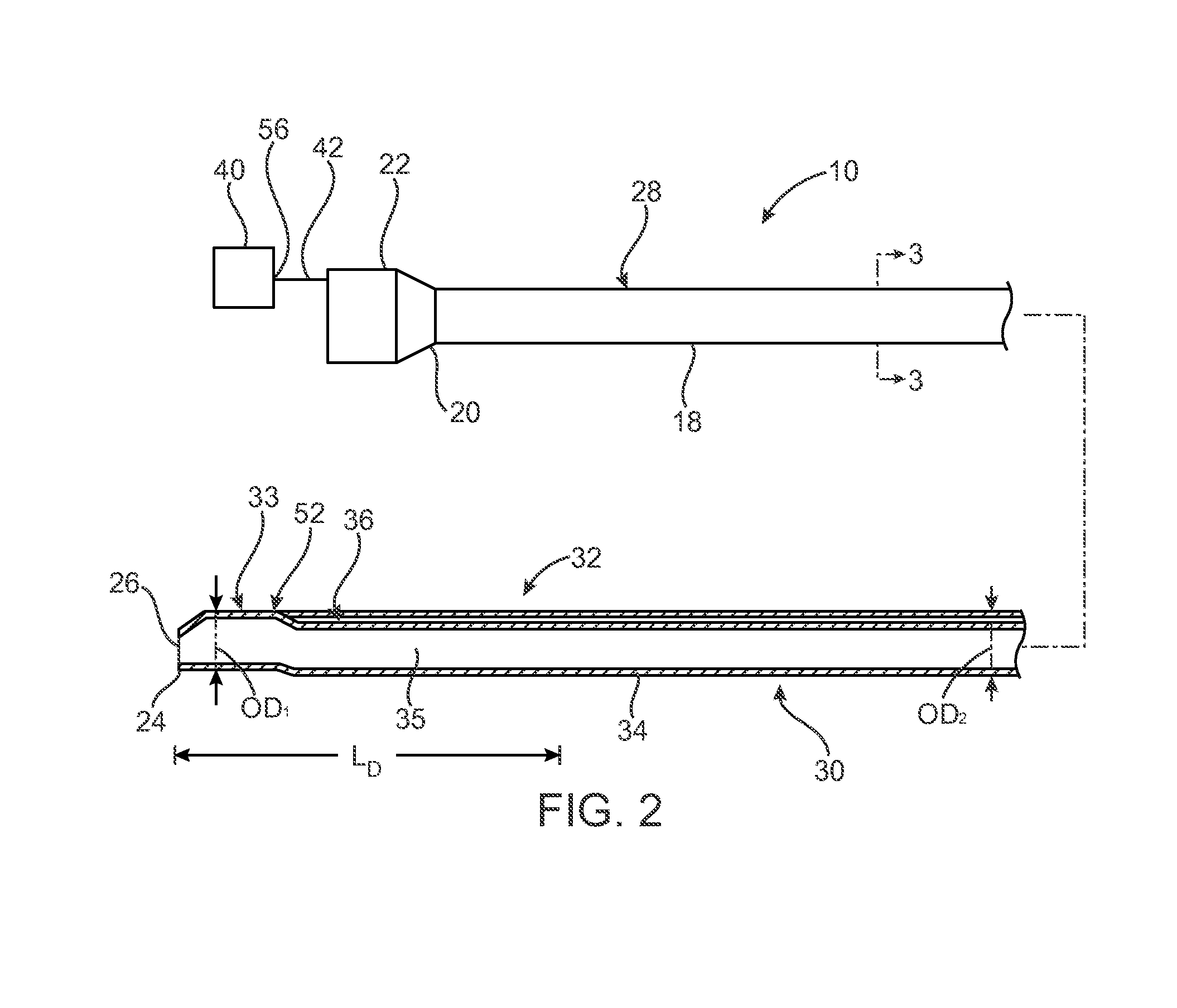
This patent describes a catheter with a pressure sensor for measuring fluid pressure in a vessel. The catheter has two separate lumens, a guide wire lumen and a pressure sensor wire lumen, which extend parallel to each other or side-by-side along the length of the catheter. At the distal end, the pressure sensor wire lumen extends to the distal tip to be coupled to a pressure sensor disposed in a pocket on the distal tip. The pressure sensor is elevated above the shaft wall and spaced apart from the sidewalls of the pocket to isolate it from bending stresses. This design is advantageous for accurately measuring fluid pressure in a vessel.

Problems solved by technology

Conventional FFR wires generally are not desired by clinicians to be used as guide wires for such interventional devices.
The mounting of a pressure sensor on the distal end of a catheter, such as a microcatheter makes it difficult to isolate the pressure sensor from bending stresses experienced as a result of interaction between the pressure sensor and the housing of the catheter.
Due to the high sensitivity and size of the pressure sensor used in this application, any stress placed on the pressure sensor can cause a distortion of the sensor resulting in an incorrect pressure reading or bend error.

Method used


Image

  • Pressure measuring catheter having reduced error from bending stresses
  • Pressure measuring catheter having reduced error from bending stresses
  • Pressure measuring catheter having reduced error from bending stresses

Examples


Embodiment Construction

[0024]Specific embodiments of the present invention are now described with reference to the figures, wherein like reference numbers indicate identical or functionally similar elements. While the disclosure refers to illustrative embodiments for particular applications, it should be understood that the disclosure is not limited thereto. Modifications can be made to the embodiments described herein without departing from the scope of the present disclosure. Those skilled in the art with access to this disclosure will recognize additional modifications, applications, and embodiments within the scope of this disclosure and additional fields in which the disclosed examples could be applied. Therefore, the following detailed description is not meant to be limiting. Further, it is understood that the systems and methods described below can be implemented in many different embodiments of hardware. Any actual hardware described is not meant to be limiting. The operation and behavior of the s...


PUM


Abstract

Bending stresses experienced by a pressure sensor mounted to a fractional flow reserve catheter when tracking the catheter through the vasculature creates a distortion of the sensor resulting in an incorrect pressure reading or bend error. In order to isolate the sensor from bending stresses, the sensor is mounted with one end coupled to the distal end of the shaft while the other end of the sensor is not coupled to the catheter so that a portion of the sensor is spaced apart from the distal end of the shaft.

Description

RELATED APPLICATIONS[0001]The present application claims the benefit under 35 U.S.C. §119 of U.S. Provisional Patent Application No. 62 / 012,628 filed on Jun. 16, 2014 and titled FFR MICROCATHETER RIGID TIP AND CANTILEVER DESIGN.FIELD OF THE INVENTION[0002]The invention relates to methods and systems for determining a pressure gradient across a lesion of a vessel for calculating a Fractional Flow Reserve.BACKGROUND OF THE INVENTION[0003]The severity of a stenosis or lesion in a blood vessel may be assessed by obtaining proximal and distal pressure measurements relative to the given stenosis and using those measurements for calculating a value of the Fractional Flow Reserve (FFR). FFR is defined as the ratio of a first pressure measurement (Pd) taken on the distal side of the lesion and to a second pressure measurement taken on the proximal side of the lesion usually within the aorta (Pa). Conventionally, a sensor is placed on the distal portion of a guidewire or FFR wire to obtain th...

Claims


Application Information

Patent Timeline
IPC IPC(8): A61B5/0215A61B5/00A61B5/02
CPCA61B5/0215A61B5/6852A61B5/02007A61B2562/0247
Inventor MCCAFFREY, GERRYSWEENEY, FIACHRAMURPHY, CHRISTOPHER
Owner MEDTRONIC VASCULAR INC
Learn More