System for compression relief shaping

a compression relief and shaping technology, applied in the field of compression relief equipment, can solve the problems of metal compressing, reducing the total surface area of the shoulder radius, etc., and achieve the effect of reducing the “ control of feature relief forming

Active Publication Date: 2015-12-17
BALL CORP
View PDF7 Cites 21 Cited by
  • Summary
  • Abstract
  • Description
  • Claims
  • Application Information

AI Technical Summary

Benefits of technology

[0007]A method and apparatus for reshaping at least one of a shoulder and a neck of a container is provided. In one embodiment, a method of reshaping a shoulder of a container is provided wherein a bottle shaped container is provided and reshaped or altered to modify either the shape o...

Problems solved by technology

Changing the shoulder radius can reduce the total surface ar...

Method used


Image

  • System for compression relief shaping
  • System for compression relief shaping
  • System for compression relief shaping

Examples


Embodiment Construction

[0035]Various embodiments of the present disclosure are described herein with reference to the drawings. It is expressly understood that although FIGS. 1-7B depict certain embodiments, the present disclosure is not limited to those specific disclosed embodiments.

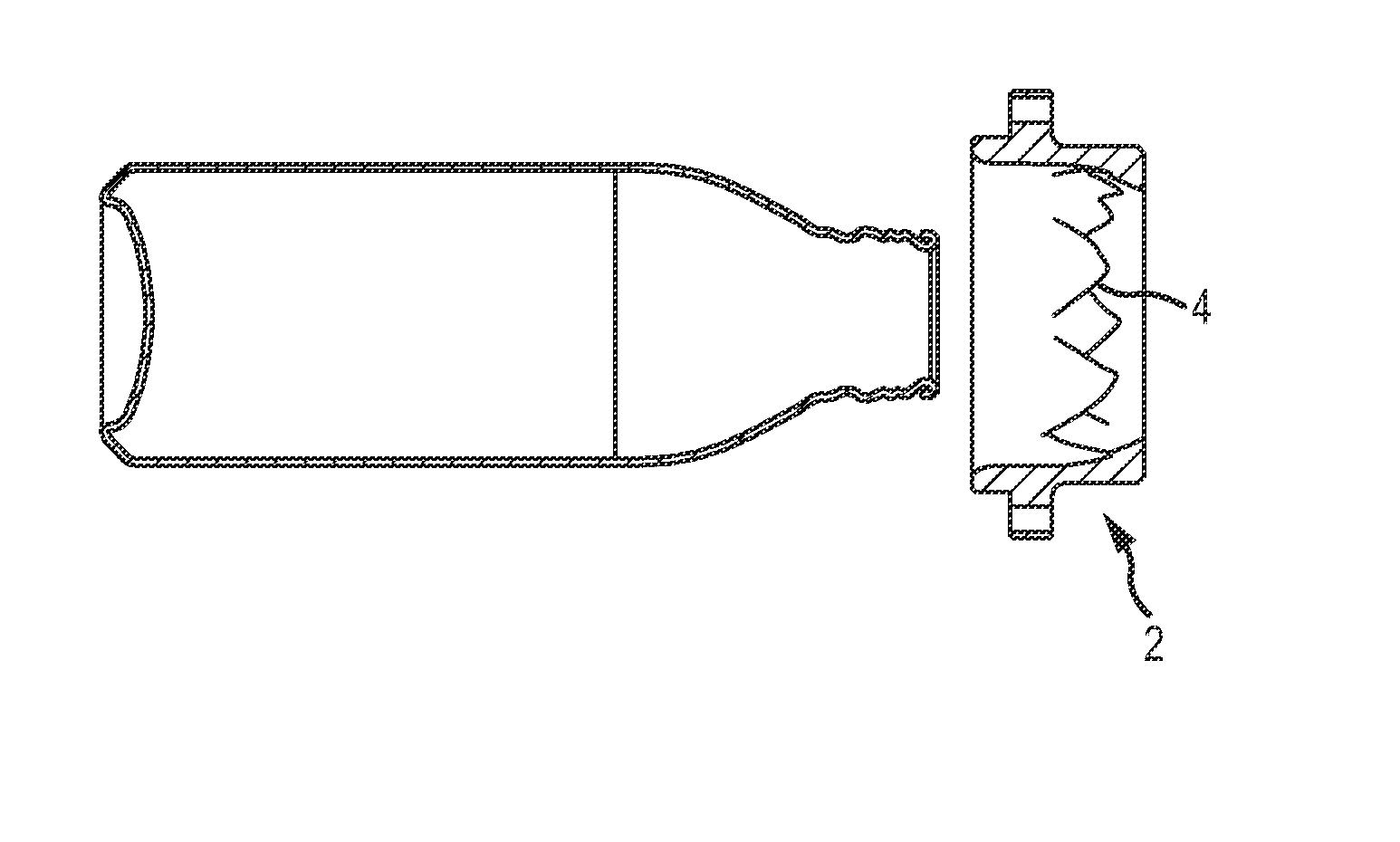
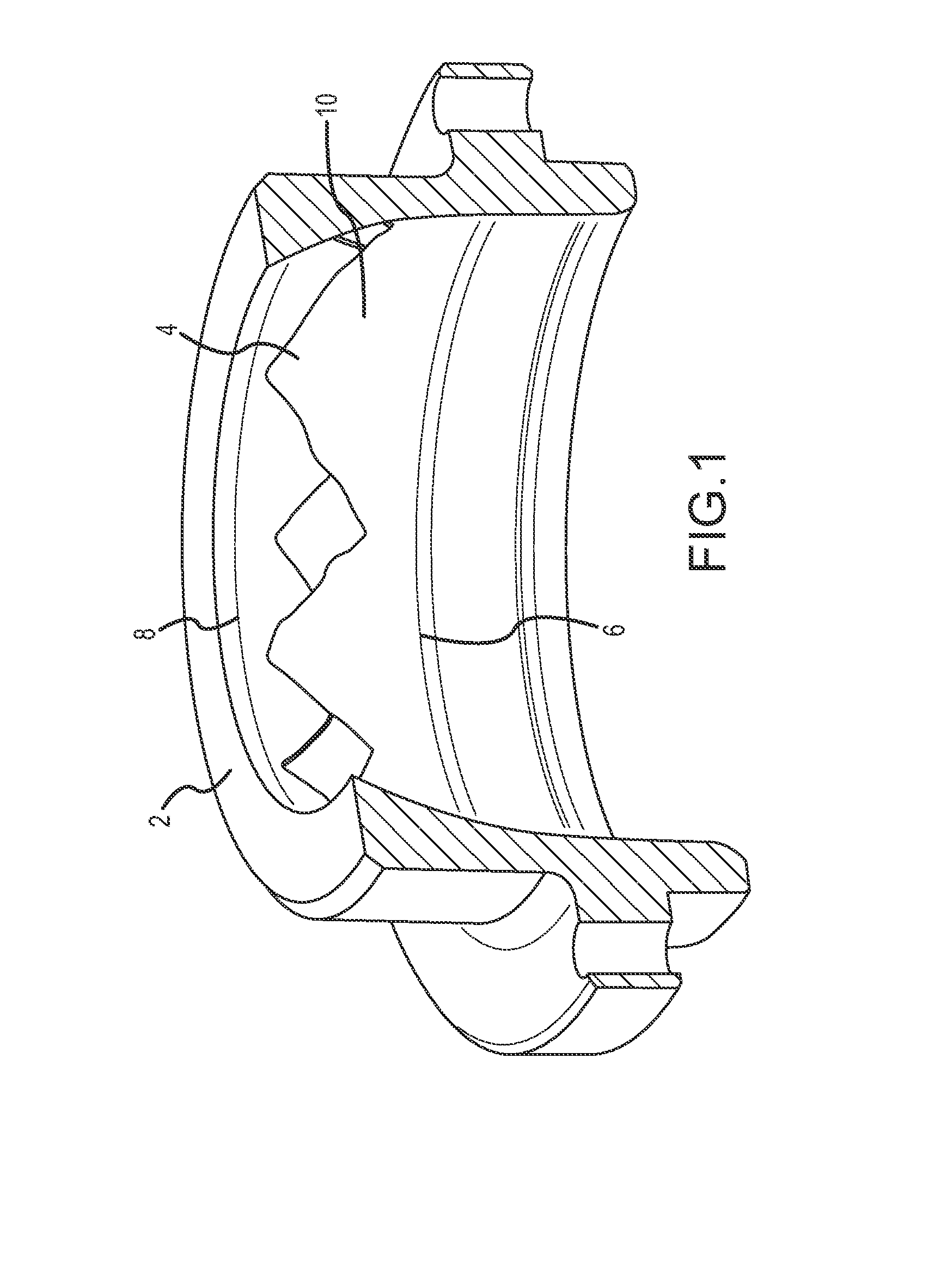
[0036]Referring now to FIG. 1, a compression relief shaping die according to one embodiment of the present invention is shown. The die 2 comprises a generally ring-shaped or annular device wherein a surface of an inner void is adapted to contact a bottle shaped metallic container during forming operations. Contact may occur with either the tool traveling toward a relatively stationary positioned metal container, or alternatively the container traveling toward the substantially stationary tool. In either scenario the tool or container travels in a substantially linear direction which is co-extensive with the longitudinal axis of the metal container. The die 2 comprises raised surface features 4 provided between shoulder radiu...


PUM

PropertyMeasurementUnit
Lengthaaaaaaaaaa
Forceaaaaaaaaaa
Sizeaaaaaaaaaa

Abstract

Methods and apparatus for reshaping a shoulder and/or neck portion of a metallic container are provided. A shoulder shaping or reshaping tool comprises a generally annular device with relief features provided on an internal surface. The tool is adapted to engage the exterior surface of a container to be shaped to provide outwardly extending ornamental features.

Description

FIELD OF THE INVENTION[0001]The present invention relates to a compression relief apparatus for applying shaped or textured features to the neck or shoulder region of a metal container. More specifically, the present invention contemplates an apparatus and method for forming predetermined shapes into the shoulder or neck of drawn and ironed aluminum bottles and cans.BACKGROUND OF THE INVENTION[0002]It is generally known in metal container manufacturing processes to provide features on metallic containers such as raised forms and indicia using opposing, offset inside and outside shaped tooling dies. Outer dies frequently comprise inward protrusions, and inner dies comprise outward protruding features. These devices are typically applied to open ended straight wall containers before necking the container. However, these processes generally do not allow for features to be formed in the neck and / or shoulder area, and existing tools and methods of manufacturing fail to provide for large ...

Claims


Application Information

Patent Timeline
IPC IPC(8): B21D51/24B21D31/00
CPCB21D31/00B21D51/24B21D51/2607B44B5/026B44C1/24B21D51/2638B21D41/00B21D26/041B21D26/033B21D26/049
Inventor JENTZSCH, KEVIN R.ROSS, JOHN R.VAN DE LIEFVOORT, MATTHIAS K.JACOBER, MARK A.
Owner BALL CORP
Why Eureka
Try Eureka