Wire harness

a wire harness and wire technology, applied in the field of wire harnesses, can solve the problems of increasing the cost of the constituent components and the wire harness, reducing the efficiency of assembling the wire harness, and reducing the mass productivity so as to prevent waste or disuse of the wire harness, prevent damage, and eliminate the labor of pulling

Active Publication Date: 2015-12-17
YAZAKI CORP
View PDF2 Cites 40 Cited by
  • Summary
  • Abstract
  • Description
  • Claims
  • Application Information

AI Technical Summary

Benefits of technology

[0012]In contrast, when the wire harness 510 illustrated in FIG. 18B is used as efforts to decrease part numbers of wire harnesses regardless of whether or not optional controlled devices are configured, the use of the wire harness 510 causes the occurrence of the device-side connectors cc3 and bb3 and electric wires as constituent components which are routed but are not actually used (so-called “disused constituent components”), and an increase in a waste of wire harnesses, thereby increasing the cost of the wire harness.
[0024]A part number of a wire harness of the present invention can be commonly used, and a waste or disuse of the wire harness can be prevented.

Problems solved by technology

The increase of part numbers of wire harnesses to be assembled causes complexity in the assembling of the wire harness in an assembly line, and a decrease in efficiency in the assembling of the wire harness.
For this reason, there is a problem in that mass productivity of the wire harness decreases, and the cost of the constituent components and the wire harness increase.
In contrast, when the wire harness 510 illustrated in FIG. 18B is used as efforts to decrease part numbers of wire harnesses regardless of whether or not optional controlled devices are configured, the use of the wire harness 510 causes the occurrence of the device-side connectors cc3 and bb3 and electric wires as constituent components which are routed but are not actually used (so-called “disused constituent components”), and an increase in a waste of wire harnesses, thereby increasing the cost of the wire harness.

Method used


Image

  • Wire harness
  • Wire harness
  • Wire harness

Examples


first embodiment

[0055]Hereinafter, the present invention is described with reference to the accompanying drawings.

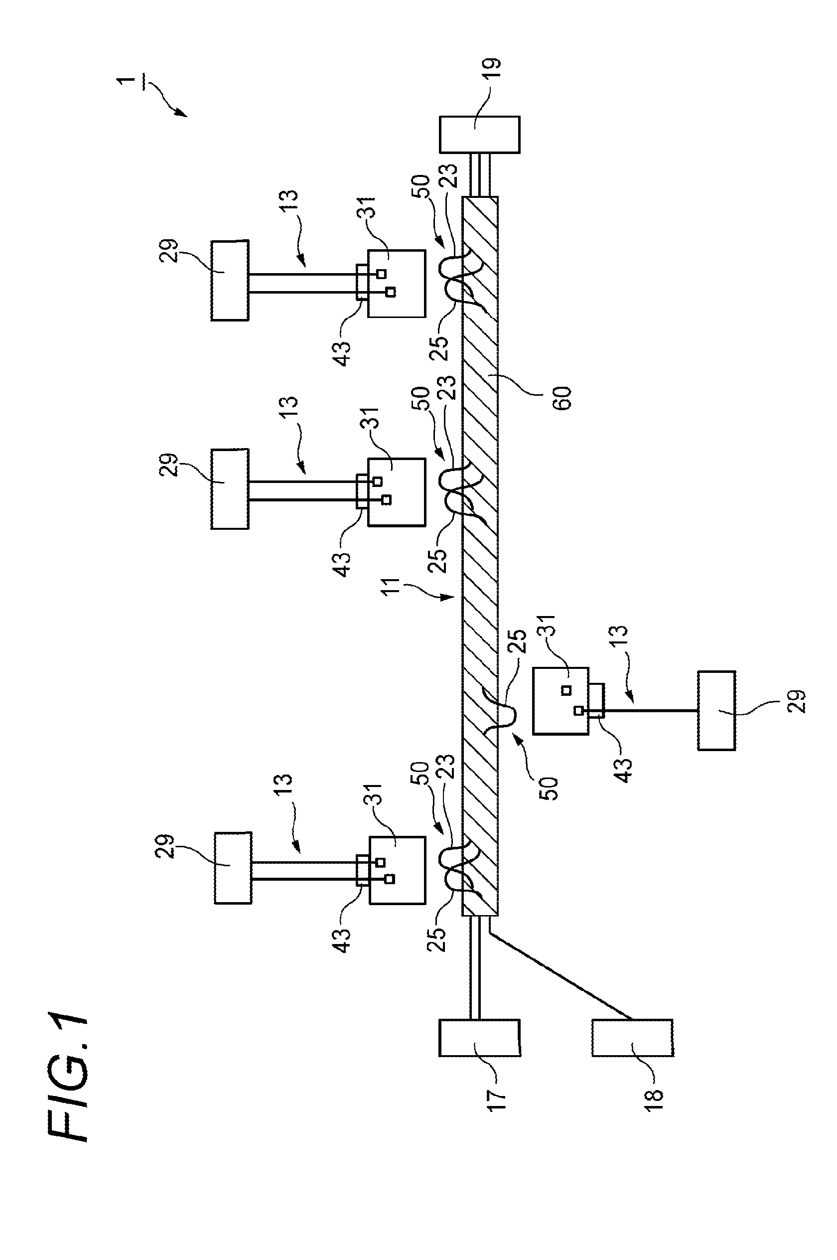
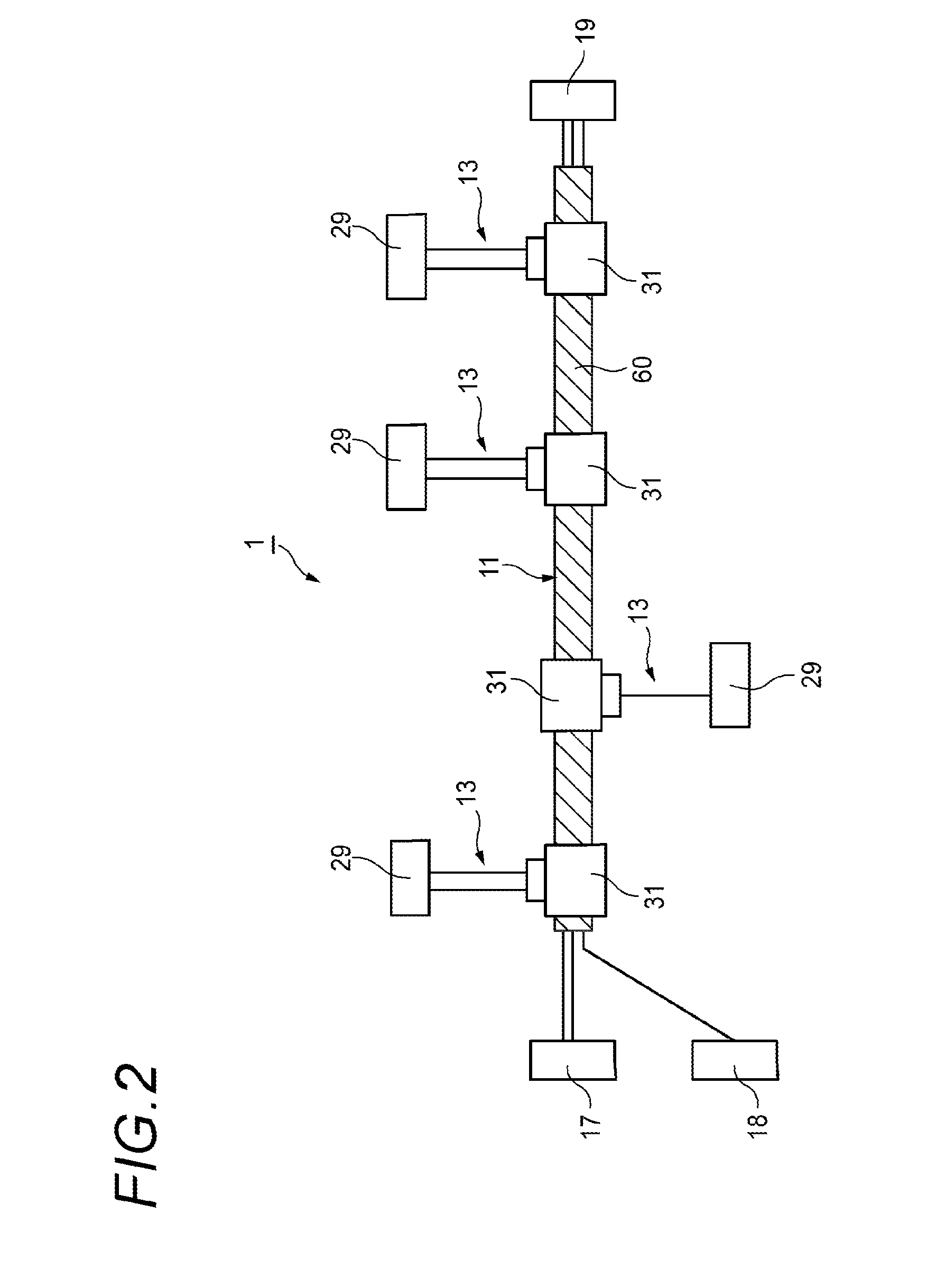
[0056]FIG. 1 is a schematic view of a wire harness according to the first embodiment of the present invention.

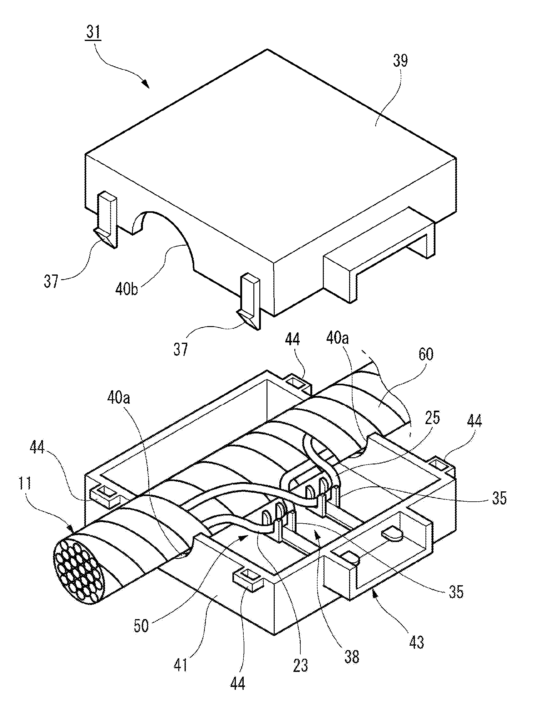
[0057]A wire harness 1 of the first embodiment has a main harness 11 to which a first end of an additional connection member 13 is later connected in a branching manner.

[0058]The main harness 11 illustrated in FIG. 1 is a bundle of four types of basic main electric wires including a power supply wire 23, a communication wire 25, a signal wire, a ground (GND) wire 27, and can be commonly installed in a plurality of installation target vehicles. The main harness 11 is connected to a plurality of electric devices (for example, a battery 17 and a joint box 19) and a connector 18. As illustrated in FIG. 1, an insulating tape 60 is wrapped around the outer circumference of the bundled electric wires of the main harness 11, and thus a plurality of the electric wires are bound together....

second embodiment

[0111]Hereinafter, the present invention is described with reference to the accompanying drawings.

[0112]FIG. 12 is a schematic view of a wire harness 101 manufactured by a wire harness manufacturing method according to the second embodiment of the present invention.

[0113]As illustrated in FIGS. 12 and 13, the wire harness 101 of the second embodiment includes three sub harnesses 111A, 111B, and 111C. Root ends (left ends in FIG. 12 or FIG. 13) of the sub harnesses 111A, 111B, and 111C have the connectors a1, b1, and c1 connected to control units (not illustrated), respectively, and branch ends (right ends in FIG. 12 or FIG. 13) thereof have the device-side connectors a2, b2, and c2 connected to destined connectors of controlled devices (electrical devices), which are targets controlled by the control units, respectively.

[0114]Each of the sub harnesses 111A, 111B, and 111C of the second embodiment is a main harness that can be commonly installed in a plurality of installation target ...


PUM


Abstract

A wire harness includes a main harness that can be commonly installed in a plurality of installation target vehicles, and a branch connection portion that is visually identifiably provided at a predetermined location on at least any one of a communication wire, a power supply wire, a signal wire, and a ground wire of the main harness. An additional connection member, connected to at least one electrical device that is actually installed in one of the plurality of installation target vehicles, is later connectable to the branch connection portion in a branching manner.

Description

CROSS REFERENCE TO RELATED APPLICATION(S)[0001]This application is based upon and claims the benefit of priorities of Japanese Patent Applications No. 2014-124373 and No. 2014-124374, both filed on Jun. 17, 2014, the contents of which are incorporated herein by reference in its entirety.BACKGROUND OF THE INVENTION[0002]1. Field of the Invention[0003]The present invention relates to a wire harness.[0004]2. Description of the Related Art[0005]A number of various electrical devices, for example, lamps, motors, and switch units for operating these lamps and motors, are mounted in a vehicle. Each of these various electrical devices is connected to a wire harness through which electric power from a battery or the like and a control signal for controlling the electrical device are supplied to the electrical device. The wire harness is made of a plurality of electric wires, connectors, and the like. The electric wire includes a core wire and an insulating coating portion that coats the core...

Claims


Application Information

Patent Timeline
Patent Type & Authority Applications(United States)
IPC IPC(8): B60R16/02
CPCB60R16/0207H01R9/031H01R11/20
Inventor SASAKI, NORIAKIYAMASHITA, TOSHIAKI
Owner YAZAKI CORP
Why Eureka
Try Eureka