Shift Knob Structure

a technology of shifting knob and shaft, which is applied in the direction of mechanical control devices, process and machine control, instruments, etc., can solve the problems of affecting workability, damage to the side surface, etc., and achieve the effect of convenient attachment to the sha

Active Publication Date: 2015-12-17
TOYOTA JIDOSHA KK
View PDF6 Cites 11 Cited by
  • Summary
  • Abstract
  • Description
  • Claims
  • Application Information

AI Technical Summary

Benefits of technology

[0008]The present invention addresses the issue and a purpose thereof is to provide a shift knob structure in which the shift knob body can be easily attached to and detached from the shift shaft, and, in particular, a shift knob structure in which the shift knob body can be easily removed from the shift shaft.
[0010]According to this embodiment, there is provided a shift knob structure in which the securing member can be unlocked from the locking groove in the shaft by rotating the cover member relative to the shift knob body. The shift knob structure makes it unnecessary to remove the securing member from the shift knob body and makes it possible for the operator to remove the shift knob structure from the shaft by rotating the cover member relative to the shift knob body, with the securing member remaining mounted to the shift knob body. Therefore, workability will be improved.
[0017]According to this embodiment, there is provided a shift knob structure capable of restricting movement of the shift knob body in the direction of shaft axis, by using a simple structure in which the securing member deformable in the direction of shaft radius is locked by the single locking groove in the shaft. According to the shift knob structure, relative rotation of the shift knob body and the shaft is restricted by the rotation stopper member formed in the insertion hole being inserted into the pair of notch grooves in the shaft. Therefore, the shift knob structure which can be easily attached to the shaft is realized.

Problems solved by technology

As such, the related-art structure leaves much to be desired in terms of workability.
This creates an additional problem in that the side surface of the shift lever between the position thereon aligned with the lower end of the cover occurring when the cover member is mounted on the shift knob body and the position occurring when the cover member is moved downward in order to remove the pin member is not suitable to form a design in consideration of the possibility that the cover member sliding along the side surface of the shift lever may damage the side surface.

Method used


Image

  • Shift Knob Structure
  • Shift Knob Structure
  • Shift Knob Structure

Examples


Embodiment Construction

[0028]The invention will now be described by reference to the preferred embodiments. This does not intend to limit the scope of the present invention, but to exemplify the invention.

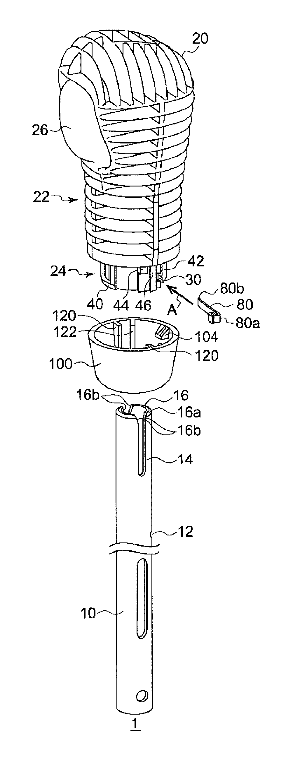
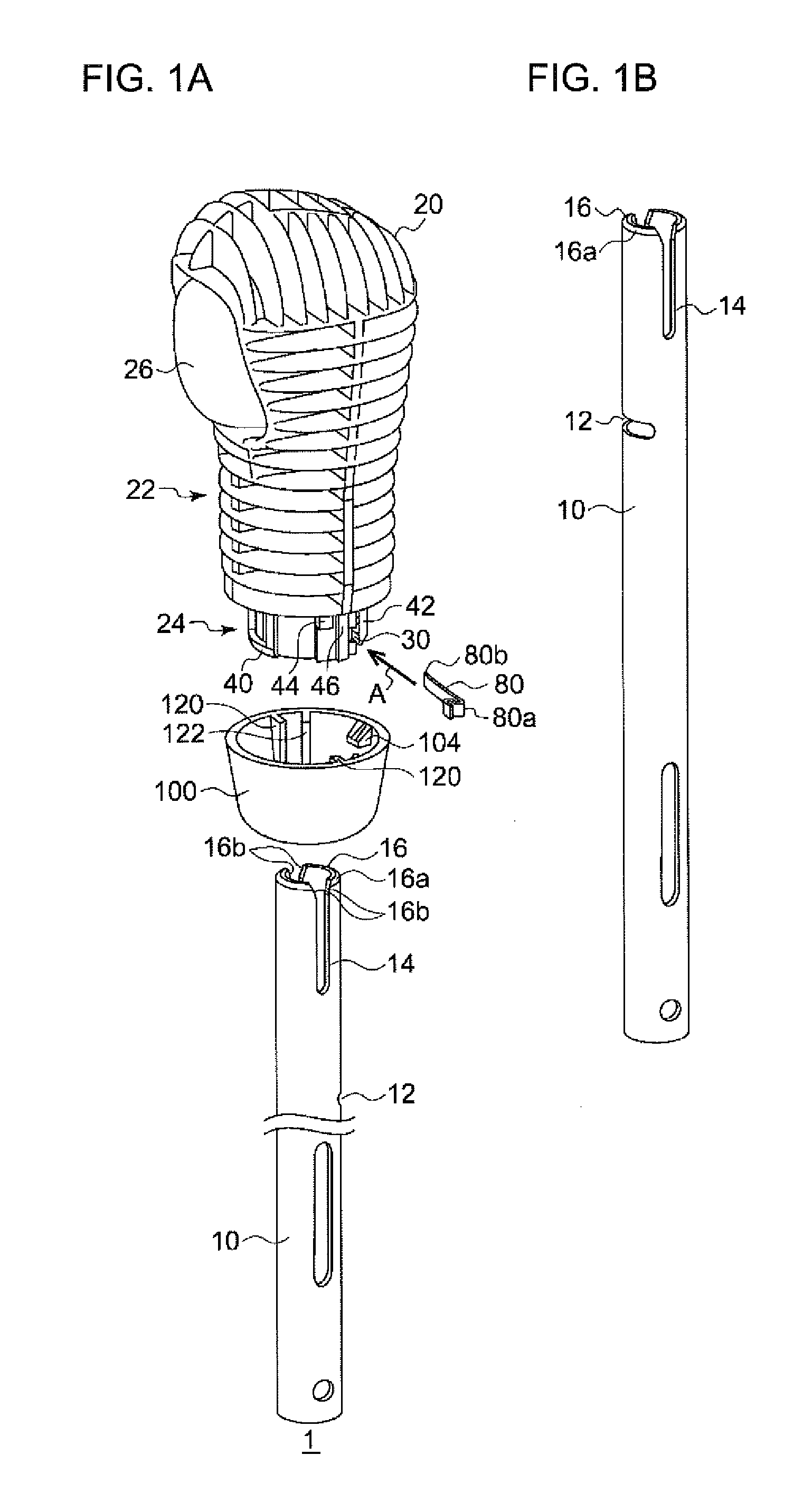
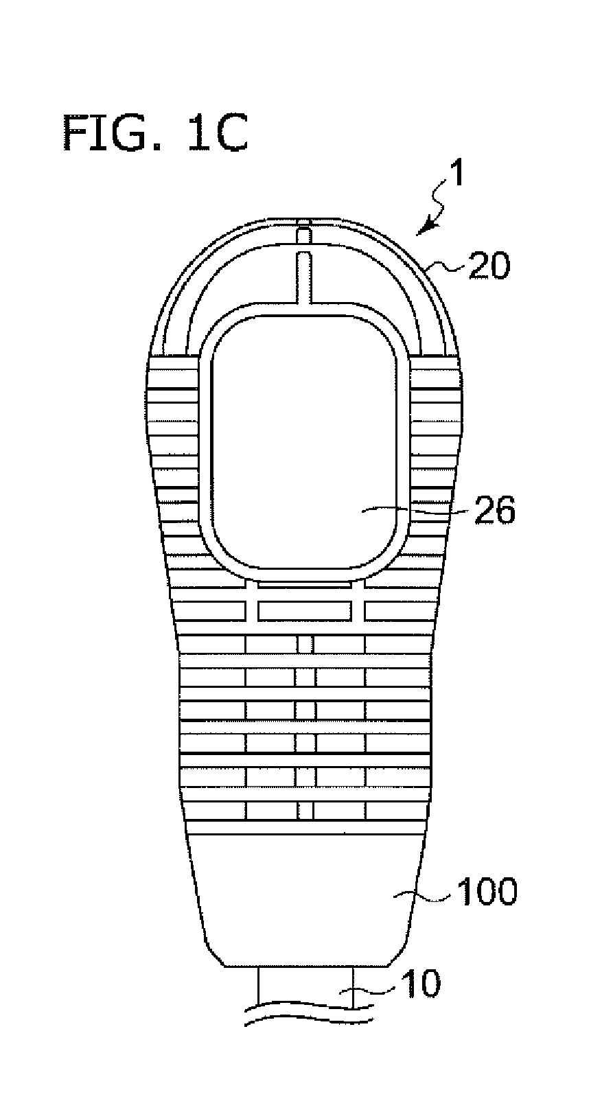
[0029]FIG. 1A is an exploded perspective view showing the shift knob structure according to an embodiment of the present invention. A shift knob structure 1 according to the embodiment is provided with a shift knob body 20 manipulated by a driver, and a cover member 100 mounted to the lower portion of the shift knob body 20. The shift knob structure 1 is mounted on top of the shift shaft 10 of a vehicle transmission. For this purpose, the cover member 100 is provided with an opening through which the shift shaft 10 is inserted, and the shift knob body 20 is provided with an insertion hole through which the shift shaft 10 is inserted.

[0030]The shift knob body 20 is provided with a grip 22 gripped by the driver by the hand for manipulation, and a lower end portion 24 formed below the grip 22. A button unit...


PUM


Abstract

A shift knob structure includes a shift knob body and a cover member. Movement of the shift knob body in a direction of shaft axis is restricted by a securing member supported by a support part of the shift knob body being locked by a locking groove in the shift shaft. When the cover member is rotated relative to the shaft knob body, the securing member is deformed radially outward and the securing member is unlocked from the locking groove in the shift shaft so that the shift knob body can be removed from the shift shaft.

Description

BACKGROUND OF THE INVENTION[0001]1. Field of the Invention[0002]The present invention relates to a shift knob structure mounted to a shift shaft of a vehicle transmission.[0003]2. Description of the Related Art[0004]Various shift knob structures mounted on upper part of the shift shaft (shift lever) have been proposed in the past. Patent document 1 discloses a shift knob mounting structure in which a pair of left and right locking grooves are formed on the outer circumference of the shift lever, and a substantially Ω-shaped pin member is mounted to a pair of left and right pin fitting grooves provided in the lower cylindrical portion of the shift knob body. In the shift knob mounting structure disclosed in patent document 1, the top of the shift lever is inserted into the insertion hole of the shift knob body. When the pin member reaches the pair of locking grooves formed in the shift lever, a pair of curved locking portions of the pin member are set and locked in the locking groove...

Claims


Application Information

Patent Timeline
Patent Type & Authority Applications(United States)
IPC IPC(8): F16H59/02F16H59/04
CPCF16H59/0278Y10T74/2014F16H59/04G05G1/06G05G1/12
Inventor NISHIJIMA, NAOTOKATO, SHORI
Owner TOYOTA JIDOSHA KK
Why Eureka
Try Eureka