Light mixing chamber for use with color converting material and light guide plate and assembly

a technology of light guide plate and light mixing chamber, which is applied in the direction of lighting and heating apparatus, planar/plate-like light guides, instruments, etc., can solve the problems of loss of efficiency and distortion of backlight color uniformity, and achieve the effect of improving efficiency and color uniformity, reducing the loss of efficiency, and widening the color gamut of backlights

Active Publication Date: 2015-12-17
SAMSUNG ELECTRONICS CO LTD
View PDF1 Cites 20 Cited by
  • Summary
  • Abstract
  • Description
  • Claims
  • Application Information

AI Technical Summary

Benefits of technology

[0004]In the invention described herein, the light generating portion of the backlight utilizes one or more discrete LEDs emitting at higher frequencies (e.g., ultraviolet or blue) that excite a remotely located color converting material containing color converting elements, such as quantum dots (semiconductor nanocrystals), which convert some portion of the higher frequency light to lower frequency visible light (e.g., green and red). The combination of the higher frequency light passing through and / or around the outside of the color converting material and the shorter frequency light emitted by the color converting material gives white light. The narrow spectral bandwidth of the emission peaks of the quantum dots enables higher efficiency and / or wider color gamut backlights as compared with the standard white LED solution. One way to introduce quantum dots (QDs) or other color converting elements into a backlight unit (BLU) is to place them along one or more edges of the BLU, between the higher frequency LED illumination and the light guide plate face. However, light that passes from the LED through the color converting material to the light guide plate is multiply scattered and reflected, leading to a loss of efficiency and distortion of the backlight color uniformity. An appropriate optical system between the LED and the light guide plate face can be designed to improve efficiency and color uniformity or provide a desired balance between efficiency and color uniformity.

Problems solved by technology

However, light that passes from the LED through the color converting material to the light guide plate is multiply scattered and reflected, leading to a loss of efficiency and distortion of the backlight color uniformity.

Method used


Image

  • Light mixing chamber for use with color converting material and light guide plate and assembly
  • Light mixing chamber for use with color converting material and light guide plate and assembly
  • Light mixing chamber for use with color converting material and light guide plate and assembly

Examples


Embodiment Construction

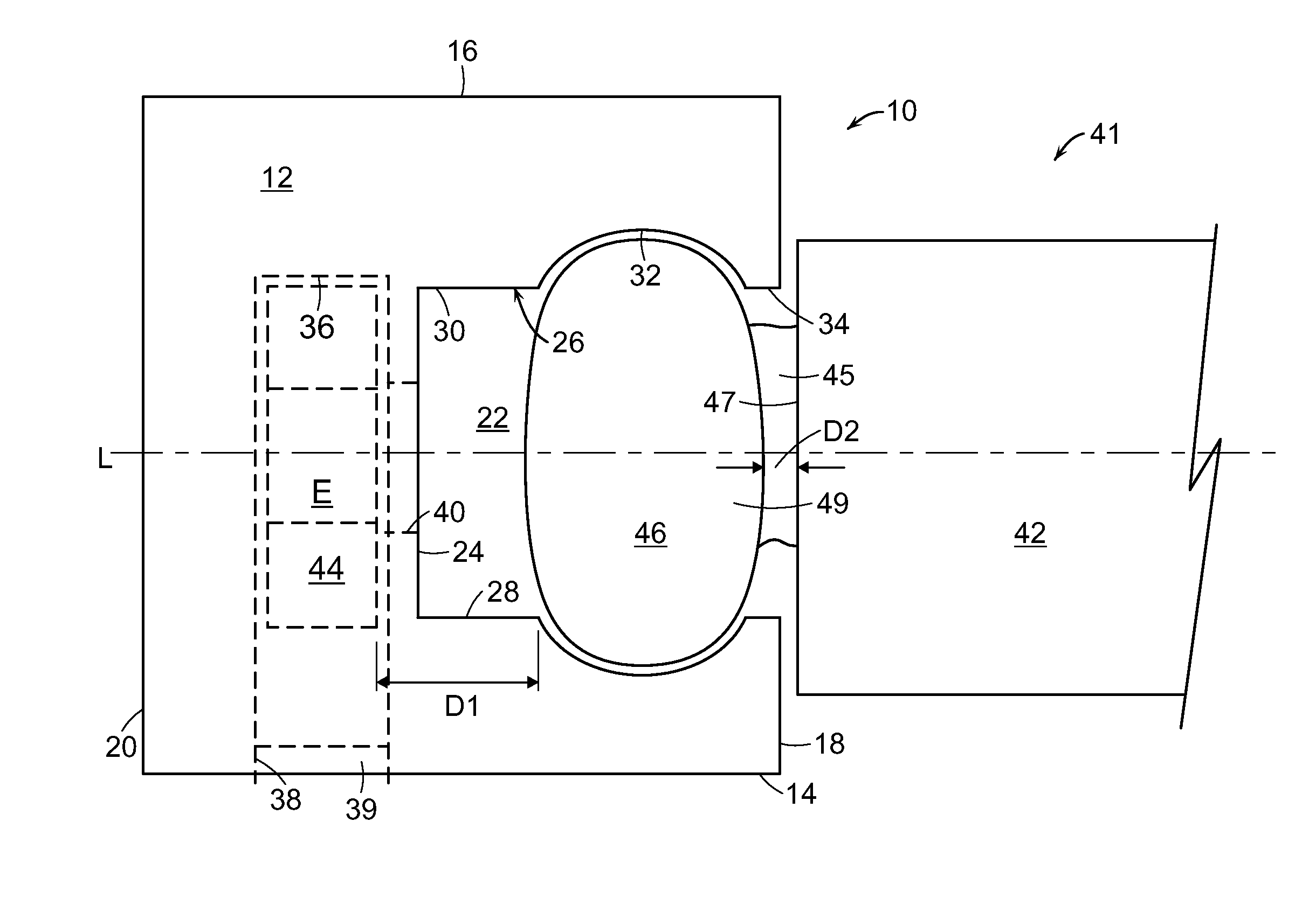
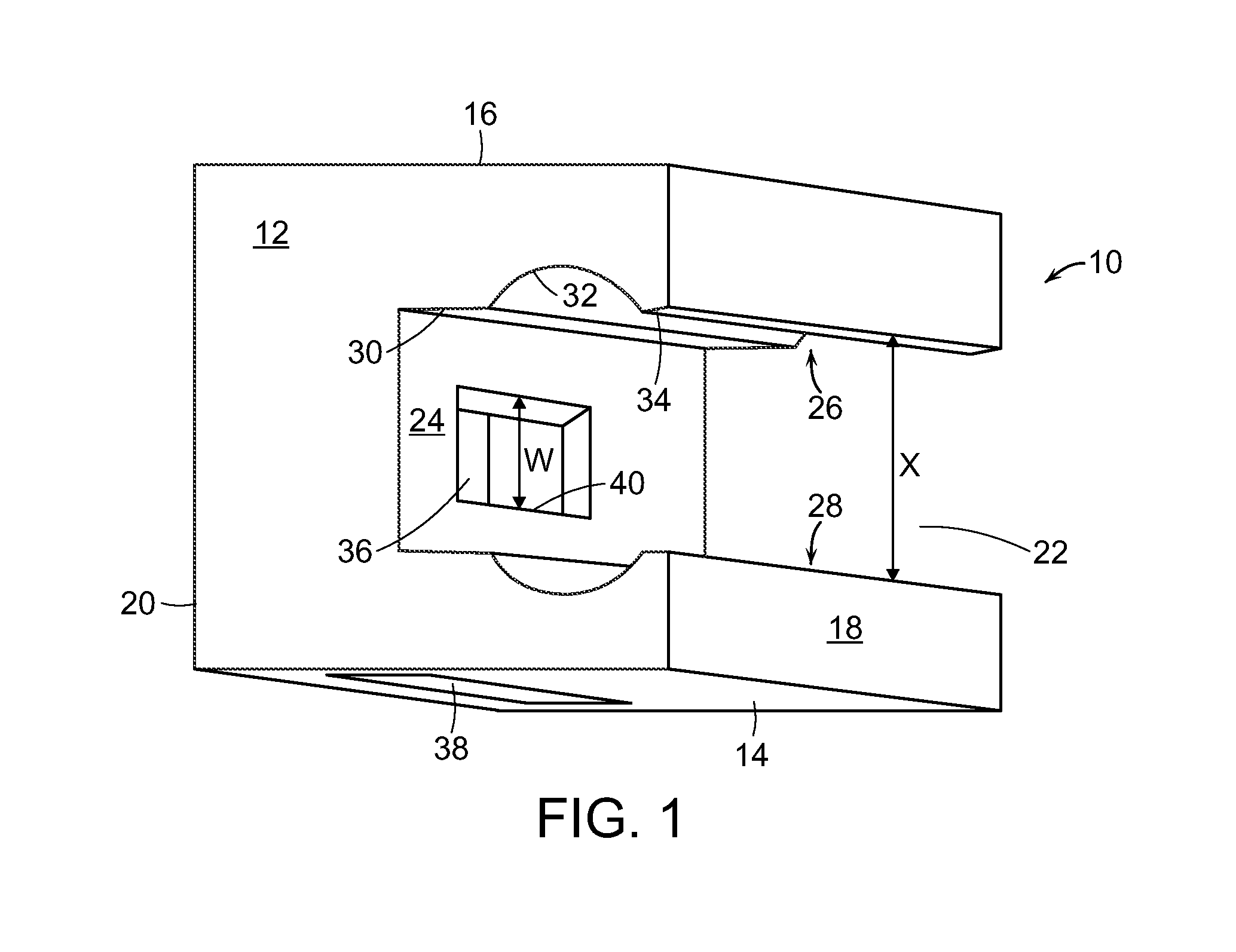
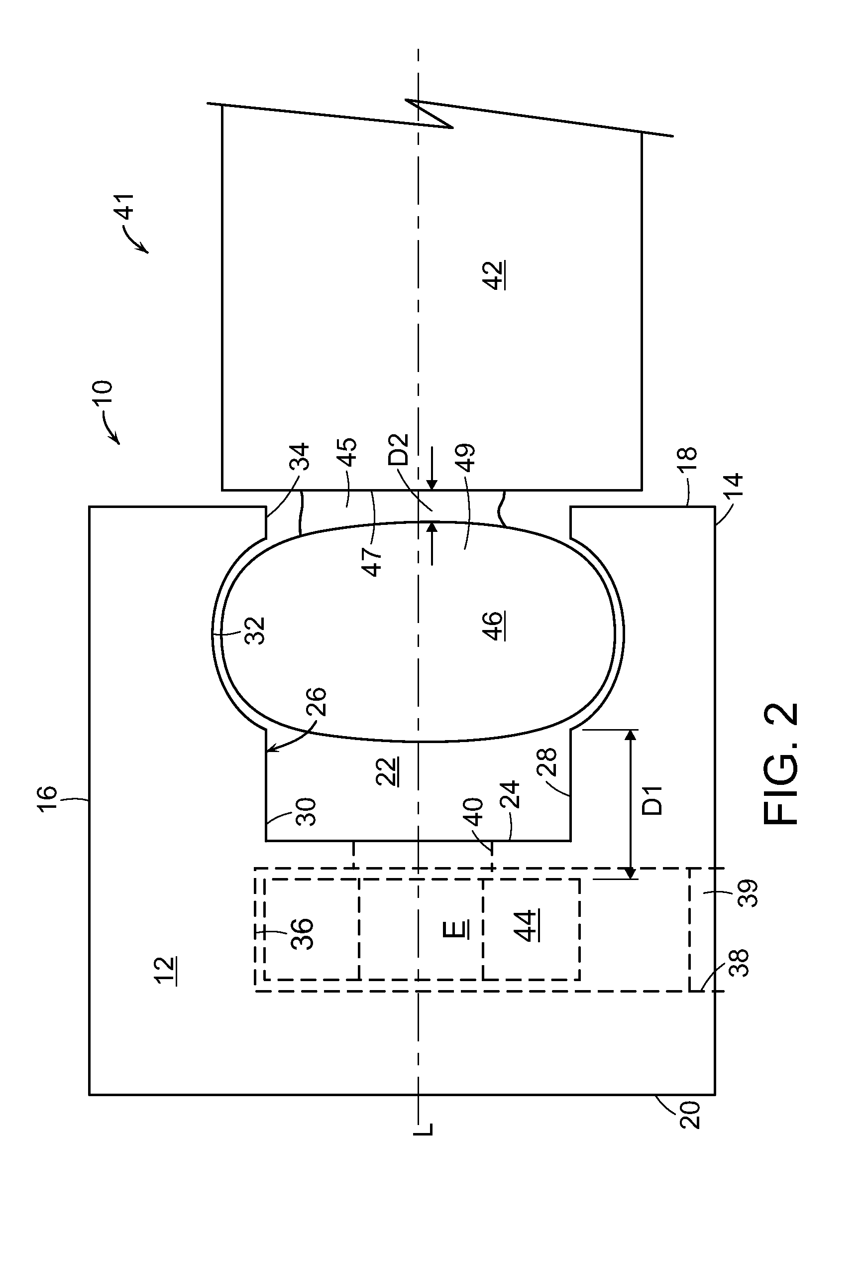
[0031]The following discussion and accompanying figures disclose a light mixing chamber for use with a light guide plate in an LED backlight. An individual skilled in the relevant art will appreciate, given the benefit of this specification, that the concepts disclosed herein with regard to the light mixing chamber may apply to a wide variety of light applications, in addition to the specific embodiments discussed in the following material and depicted in the accompanying figures.

[0032]A light mixing chamber 10 for use with a light guide plate in a backlight is depicted in FIG. 1 as including a housing 12 having a first side or surface 14 and an opposed second side or surface 16. In the illustrated embodiment, first surface 14 and second surface 16 are substantially planar surfaces and extend substantially parallel to one another. Both a third side or surface 18 and an opposed fourth side or surface 20 extend between first and second surfaces 14, 16. In the illustrated embodiment, t...


PUM


Abstract

A light mixing chamber of a backlight includes a housing having a channel and a chamber exposed to the channel, an LED positioned within the chamber, and a capillary containing quantum dots positioned in the channel. A light guide plate is positioned adjacent the housing and adjacent the capillary. Relative dimensions of the elements of the light mixing chamber, as well as features added to the elements of the light mixing chamber, can be varied to balance efficiency and uniformity of light generated in the backlight.

Description

[0001]This application claims priority to U.S. Provisional Patent Application No. 62 / 010,602, filed 11 Jun. 2014, which is hereby incorporated herein by reference in its entirety for all purposes.TECHNICAL FIELD OF THE INVENTION[0002]Aspects of this invention relate generally to a light mixing chamber and, in particular, to a light mixing chamber for use with a LED, a capillary filled with color converting material housed within the chamber, and a light guide plate of a backlight.BACKGROUND OF THE INVENTION[0003]Backlights are used for illumination in liquid crystal displays (LCDs) and may use light emitting diodes (LEDs) as the light source. The light from an LED is injected into a light guide plate which distributes the light evenly in the backplane of the backlight. Standard backlights utilize a white LED in the light generating portion of the backlight. The white LED is typically an assembly including a light emitting semiconductor die emitting at higher frequency (e.g., ultravi...

Claims


Application Information

Patent Timeline
Patent Type & Authority Applications(United States)
IPC IPC(8): F21V8/00
CPCG02B6/0026G02B6/0031G02B6/003B82Y20/00G02B6/009Y10S977/774G02B6/0073G02B6/0023
Inventor SADASIVAN, SRIDHARTWIETMEYER, KARENPUMYEA, WARREN P.HINCHEY, VICTORIA K.
Owner SAMSUNG ELECTRONICS CO LTD
Why Eureka
Try Eureka