
Semitransparent diffusion-polarization laminate and usage therefor

a diffusion-polarization laminate and semi-transparent technology, applied in the direction of polarising elements, instruments, projectors, etc., can solve the problems of difficult to clearly display an image under bright natural light, failure to disclose the relation between the screen and an outside light (e.g., natural light) from the other side of the polarizer, etc., to achieve simple structure, improve front luminance, and improve image visibility

Inactive Publication Date: 2015-12-17
DAICEL CHEM IND LTD
View PDF2 Cites 37 Cited by
  • Summary
  • Abstract
  • Description
  • Claims
  • Application Information

AI Technical Summary

Benefits of technology

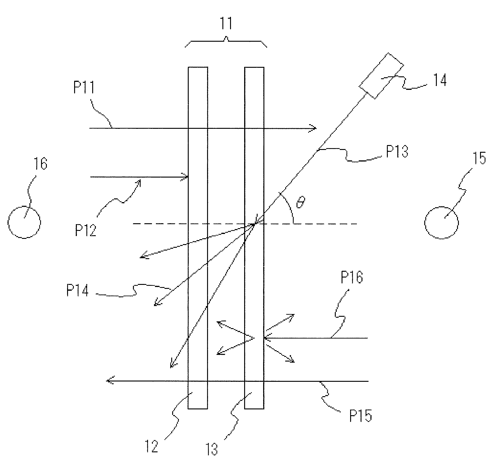
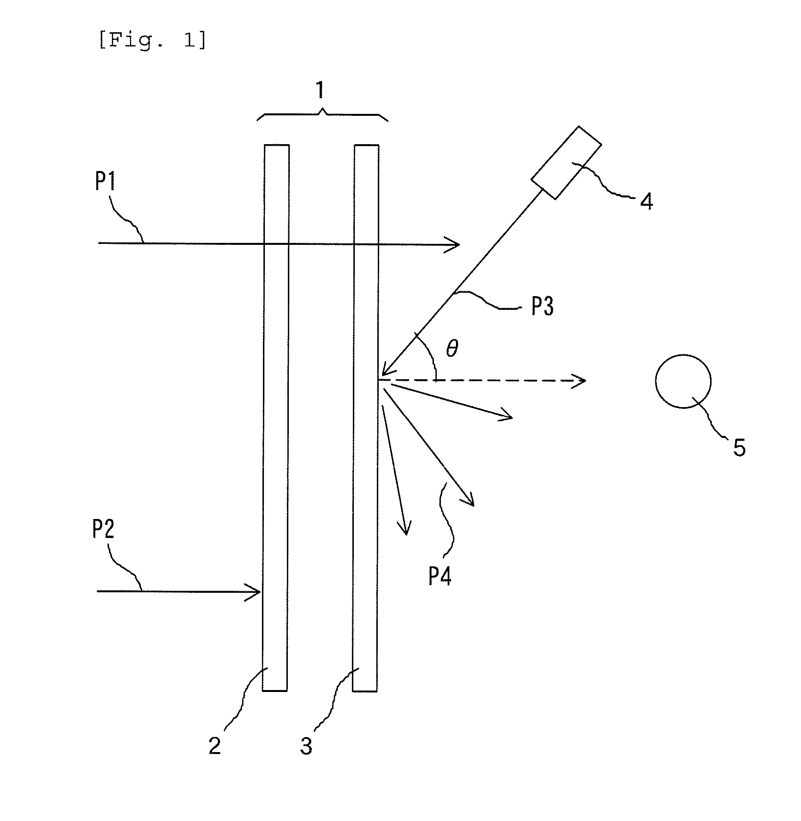
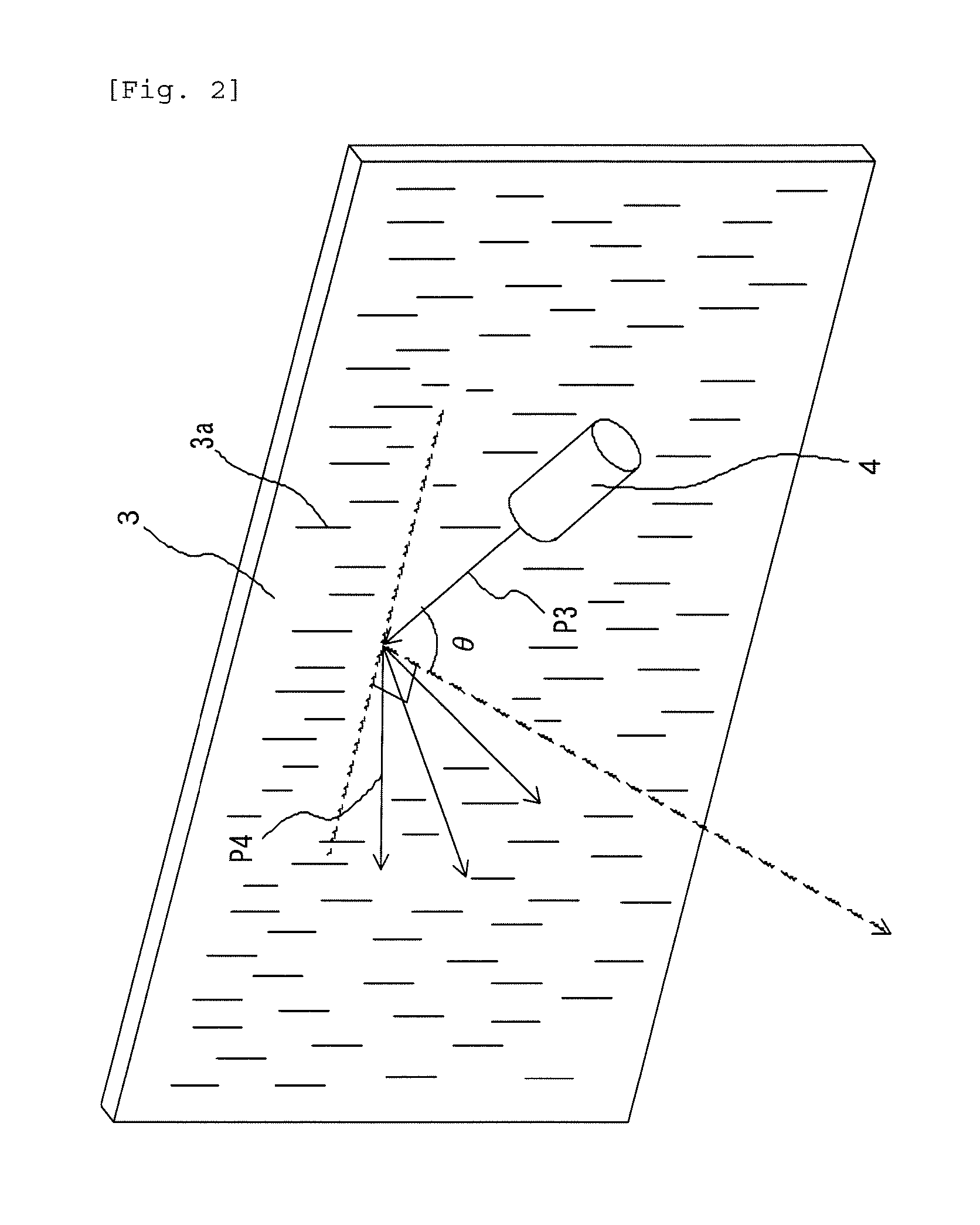
The present invention provides a translucent projector screen that allows a transmission image (view of the other side of the screen) to be distinctly seen through and maintains the visibility of a projection image from a projector even in a case where the image is projected on the screen from a projector at a wide angle of incidence. Moreover, the polarization laminate is thin and light and can be used for both reflective and transmissive screens, allowing a distinct view to be seen through from both inside and outside of a room or vehicle, independent of the projection of an image from a projector. Additionally, the absorption polarization layer can reduce the influence of ambient brightness and a light-control layer can regulate a decrease in light intensity to improve the visibility of the image in both the daytime and nighttime.

Problems solved by technology

Unfortunately, the hologram screen cannot discriminate a natural light from an artificial light (polarized light) due to no polarization selectivity, and it is difficult to clearly display an image under a bright natural light.
The half-mirror screen unavoidably has a structural shortcoming of obstructing part of the field of view, and in principle, the half-mirror screen is difficult to increase in size.
However, these documents only disclose improvement of a polarized-light-separating function of the polarized-light selective reflection layer as the role of the absorption polarizer and fail to disclose the relation between the screen and an outside light (e.g., a natural light) from the other side of the polarizer.
Thus, in a case where a light enters at a wide angle from a projector (in a case where an angle of incidence is large), the reflective screen has a reduced front luminance and cannot display a distinct image.
For that reason, the reflective screen is unsuitable for an application in which a light enters at a large angle of incidence from a projector to the screen (for example, a short throw projector, such as HMD).
Moreover, since the polarizable diffusion film has an islands-in-the-sea structure formed according to a difference in crystallinity of a single crystalline resin, it is difficult to control a refractive index of the film and to improve scattering characteristics or polarization characteristics.
Thus, it is difficult to apply the polarizable diffusion film to the translucent screen.
Moreover, an increase in the illuminance of the light source of the projector is economically and environmentally inefficient due to increased electricity consumption thereof.
In particular, for the translucent screen, it is structurally difficult to be compatible with the visibility of a transmission image (a view of the other side of the screen with respect to an observer, an outdoor or indoor view) and the visibility of an image projected on the screen (a projection image).
In a case where there is a large difference in illuminance (light intensity) between the inside and outside of a room, both visibilities are particularly difficult to be compatible.
For example, when the translucent screen is used for a window of a vehicle (e.g., an automobile), an exterior window of a building, or others and the sunlight, having a large light intensity, as an outside light enters the window; it is difficult for an observer to see (or visually recognize) a projection image distinctly.
Specifically, the projection screens described in Patent Documents 1 to 3 cannot adjust the outside light intensity.
For that reason, in a case where there is a large difference in illuminance between the inside and outside of a room, it is impossible to distinctly see both the projection image and the view (or scenery) of the other side through the screen.
In particular, for a projector disposed in a room and a reflective translucent screen, too large an outside light intensity inhibits the improvement of the visibility of a projection image even in a case where the light intensity of the projector is increased.
Unfortunately, this document is silent on the display of an image on a window of a vehicle.

Method used


Image

  • Semitransparent diffusion-polarization laminate and usage therefor
  • Semitransparent diffusion-polarization laminate and usage therefor
  • Semitransparent diffusion-polarization laminate and usage therefor

Examples


example 1

[0196]The PEN resin (10 parts by weight) as a resin for a dispersed phase and the PC resin (90 parts by weight) as a resin for a continuous phase were melt-kneaded and extruded at a cylinder temperature of 280° C. by the biaxial extruder and cooled to give a pellet. The resulting pellet was press-molded at 270° C. and a pressure of 10 MPa for 3 minutes by the small pressing machine to give a press sheet having a thickness of 350 μm. The resulting sheet was cut to a width of 40 mm and a length of 70 mm to give a specimen. The specimen was pre-heated at a chuck distance of 50 mm at 150° C. for 5 minutes by the tensile tester provided with a thermostatic unit, stretched to 1.5 times at a tension speed of 250 mm / min., and then heat-treated at 165° C. for 3 minutes with the specimen held by the chuck. Thereafter, the specimen was rapidly cooled to a room temperature to give a stretched film. The dispersed phase in the film had a major-axis length of 1.5 μm, a minor-axis length of 0.5 μm,...

example 2

[0199]A stretched film and a polarization laminate were produced in the same manner as Example 1 except that a press sheet having a thickness of 400 μm was produced by press molding.

example 3

[0200]A stretched film and a polarization laminate were produced in the same manner as Example 1 except that a press sheet having a thickness of 550 μm was produced by press molding.


PUM


Abstract

Provided is a polarization laminate that allows a distinct transmission image to be displayed on a translucent screen while maintaining the visibility of a projection image from a projector even in a case where the translucent screen contains a diffusion-polarization plate. A transparent polarization laminate as a member of a translucent projector screen for displaying a projection image from a projector comprises a diffusion polarization layer and an absorption polarization layer, the diffusion polarization layer comprises a continuous phase comprising a first transparent thermoplastic resin and a dispersed phase comprising a second transparent thermoplastic resin and having a refractive index different from that of the continuous phase, and these layers are laminated so that the diffusion polarization layer may have a transmission axis substantially parallel with a transmission axis of the absorption polarization layer. The diffusion polarization layer may comprise a stretched sheet, the continuous phase may have an in-plane birefringence of less than 0.05, the dispersed phase may have an in-plane birefringence of not more than 0.05, and a difference in refractive index for linearly polarized light between the continuous phase and the dispersed phase in a stretching direction may be different from that in a direction perpendicular to the stretching direction.

Description

TECHNICAL FIELD[0001]The present invention relates to diffusion-polarization laminates for translucent screens of head mounted displays or window displays, translucent (semi-transmissive) projector screens comprising the laminates, and projection systems comprising the screens. The present invention also relates to methods for improving the visibility of projection images and transmission images.BACKGROUND ART[0002]Translucent screens (semi-transmissive screens or transparent reflective or transmissive screens) can display a projection image from a projector and allows visual recognition of the other side of the screen. A translucent screen is being used for a window display, a head up display (HUD), a head mounted display (HMD), and others. As the translucent screen (transparent projection screen), for example, a hologram screen and a half-mirror screen are known. Unfortunately, the hologram screen cannot discriminate a natural light from an artificial light (polarized light) due t...

Claims


Application Information

Patent Timeline
Patent Type & Authority Applications(United States)
IPC IPC(8): G02B27/01G02B27/28G03B21/604G02B5/30
CPCG02B27/0101G02B5/305G02B27/286G02B2027/0194G03B21/604G02B2027/0196G02B2027/0118G02B27/283G02B5/3033G02B27/288G03B21/62G02B5/30G02B27/0172G02B2027/0112
Inventor TEI, TAKAHIRO
Owner DAICEL CHEM IND LTD
Learn More