Drilling Template, Drilling Template Arrangement And Method For Introducing Bores
- Summary
- Abstract
- Description
- Claims
- Application Information
AI Technical Summary
Benefits of technology
Problems solved by technology
Method used
Image
Examples
first embodiment
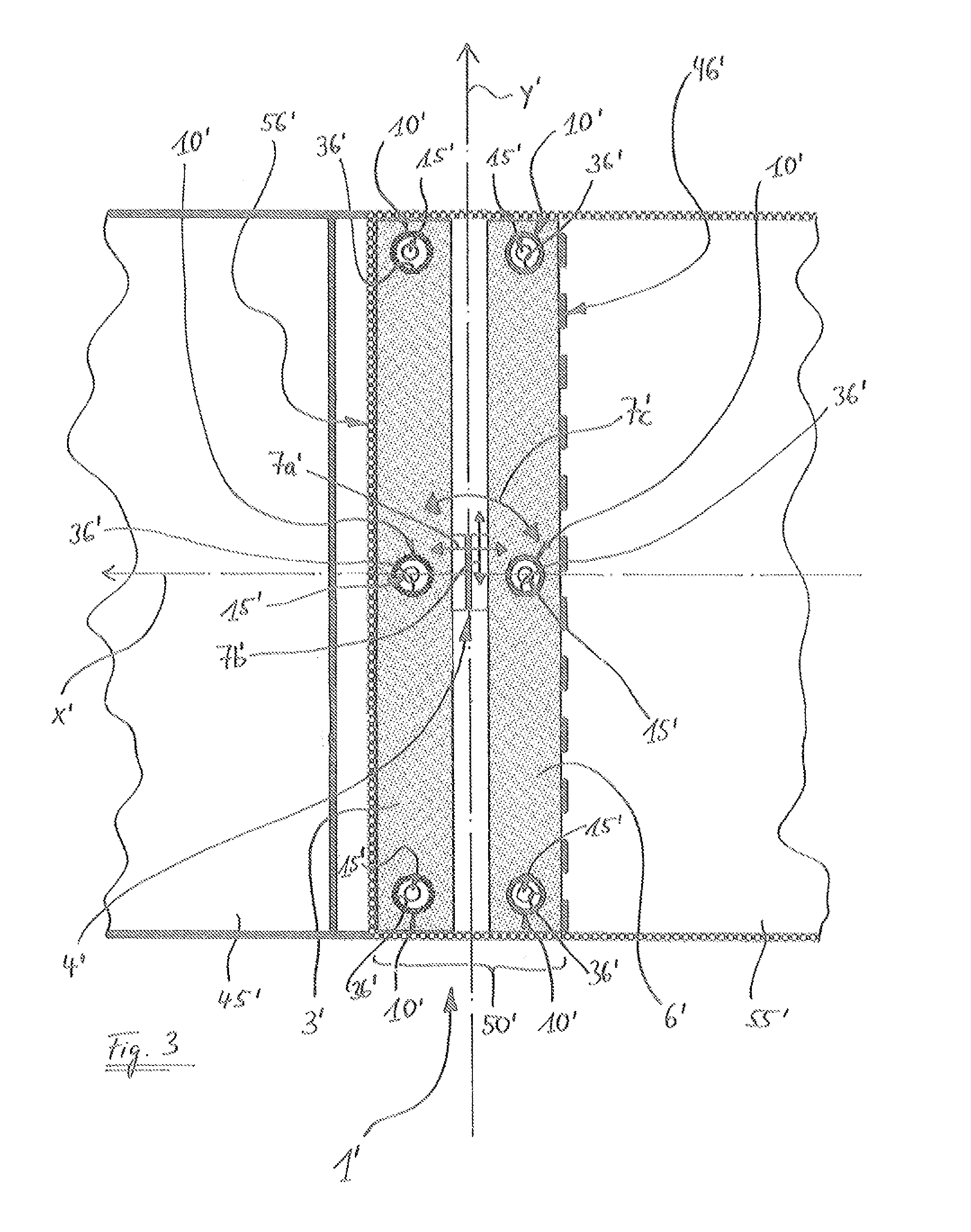
[0075]FIG. 3 shows a drilling template 1′ according to the invention, having a first template part 3′ and a second template part 6′, which are arranged in an overlapping region 50′ of two components 45′ and 55′ intended for an aircraft or spacecraft. One edge 46′ of the first component 45′ is covered in the viewing direction of FIG. 3 by the second component 55′ and therefore shown by dashed lines. The visible edge of the second component 55′ is denoted by the reference numeral 56′.
[0076]Each of the template parts 3′ and 6′ is provided in FIG. 3 with a plurality of means 10′, three in the example shown, for positioning bores 15′. With the aid of the drilling template 1′, the bores 15′ are to be drilled in the overlapping region 50′ through the first component 45′ and through the second component 55′ overlapping the first component 45′ in the overlapping region 50′ in regions. For this purpose, the means 10′ are preferably configured as through-openings 36′, in particular bores, thro...
second embodiment
[0081]A second embodiment is to be described below with reference to FIGS. 4 to 18.
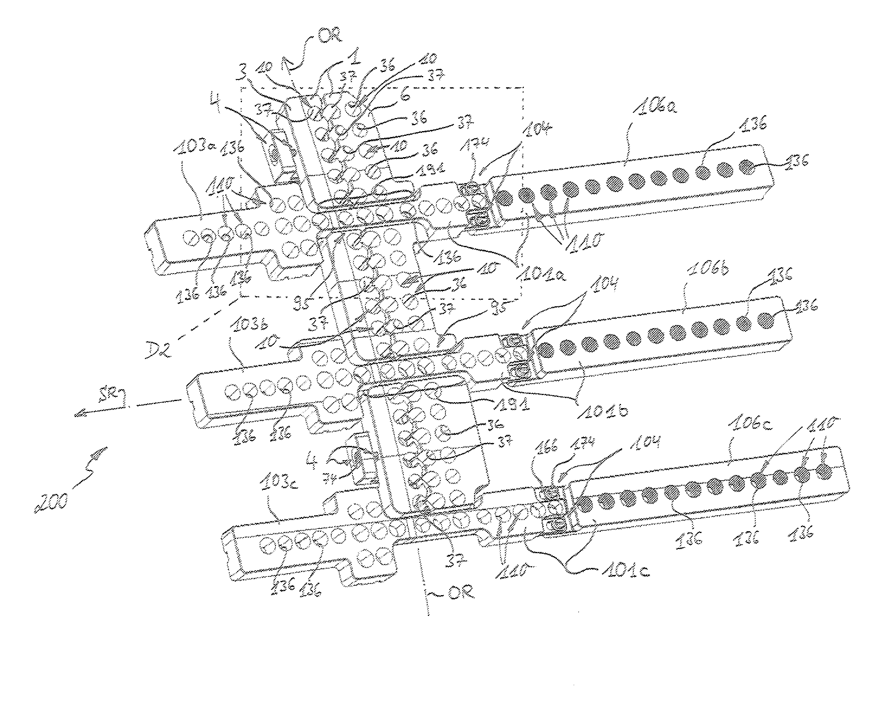
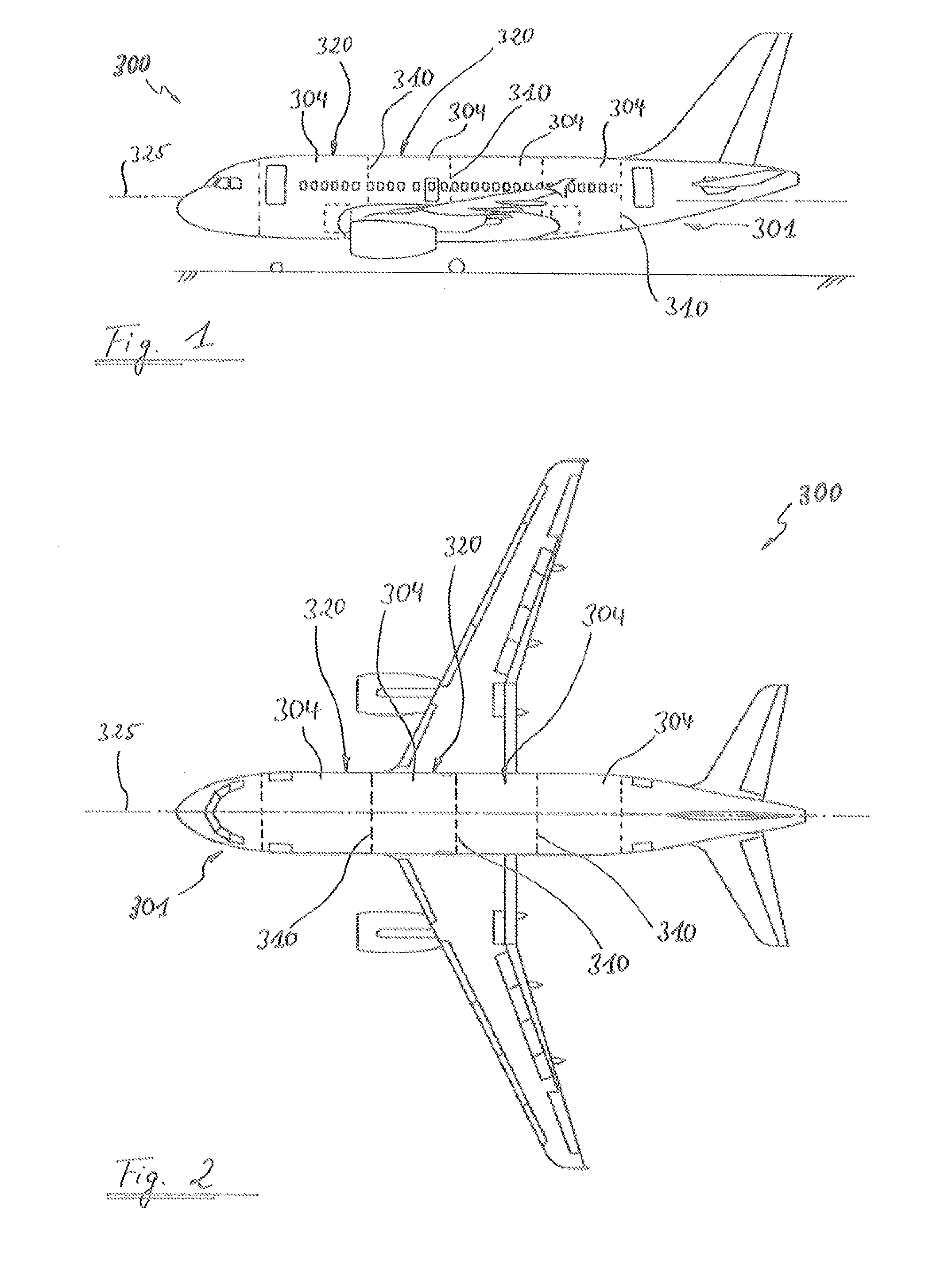
[0082]FIG. 4 shows a drilling template arrangement 200 according to the second embodiment of the invention, which has a first drilling template 1 and three second drilling templates 101a to c. The drilling template arrangement 200 is configured for use in the production of an aircraft fuselage and is used for the efficient, rapid and economic production of bores as rivet holes of high quality in the region of and close to a transverse seam 310 between two fuselage sections 304; see FIG. and 2. To produce an entire transverse or peripheral seam around the fuselage 301, a large number of drilling template arrangements 200 of the type shown in FIG. 4 can be used.
[0083]Firstly, the first drilling template 1 and the second drilling templates 101a to 101c are to be described.
[0084]The first drilling template 1 has a first template part 3 and a second template part 6. The second template part 6 is configured...
third embodiment
[0114]FIG. 19A shows a drilling template 401 according to the invention, which has a first template part 403 and a second template part 406. The template parts 403 and 406 are shown coupled to one another in FIG. 19A. Each of the template parts 403, 406 has through-openings 436 configured as bores, of which at least several, in each case, form means 410 for positioning bores 415. The first template part 403 rests displaceably on a surface 423 of a portion 421 of the second template part 406, the portion 421 being formed in the region of a recess extending in the longitudinal direction of the template part 406; see FIG. 19B. OR also denotes an orbital direction in FIG. 19A in the region of a transverse seam 310 between two fuselage sections 304 and the longitudinal direction of the template part 406 extends in the orbital direction OR. Coupling means 404 comprise screws 474, with the aid of which the first template part 403 is coupled to the second template part 406 such that the tem...
PUM
| Property | Measurement | Unit |
|---|---|---|
| Thickness | aaaaa | aaaaa |
Abstract
Description
Claims
Application Information
 - R&D
- Intellectual Property
- Life Sciences
- Materials
- Tech Scout
- Unparalleled Data Quality
- Higher Quality Content
- 60% Fewer Hallucinations
Browse by: Latest US Patents, China's latest patents, Technical Efficacy Thesaurus, Application Domain, Technology Topic, Popular Technical Reports.
© 2025 PatSnap. All rights reserved.Legal|Privacy policy|Modern Slavery Act Transparency Statement|Sitemap|About US| Contact US: help@patsnap.com


