Hydraulic valve for an internal combustion engine

a technology of internal combustion engine and hydraulic valve, which is applied in the direction of valve drives, machines/engines, non-mechanical valves, etc., can solve the problems of countless manufacturers to modify the relative timing, duration or opening of their engine's inlet and exhaust valves, and achieve the effect of reducing the negative effects

Active Publication Date: 2015-12-24
HILITE GERMANY
View PDF1 Cites 11 Cited by
  • Summary
  • Abstract
  • Description
  • Claims
  • Application Information

AI Technical Summary

Benefits of technology

[0010]The proposed design limits compression of the check valves, consequently reducing the negative effects brought about by over-compression. Additional advantages of the invention may be derived from the patent claims, the description, and the drawings.

Problems solved by technology

Especially in the automotive industry, increasingly strict environmental regulations are causing countless manufacturers to modify the relative timing, duration, or opening of their engines' inlet and exhaust valves.

Method used


Image

  • Hydraulic valve for an internal combustion engine
  • Hydraulic valve for an internal combustion engine
  • Hydraulic valve for an internal combustion engine

Examples


first embodiment

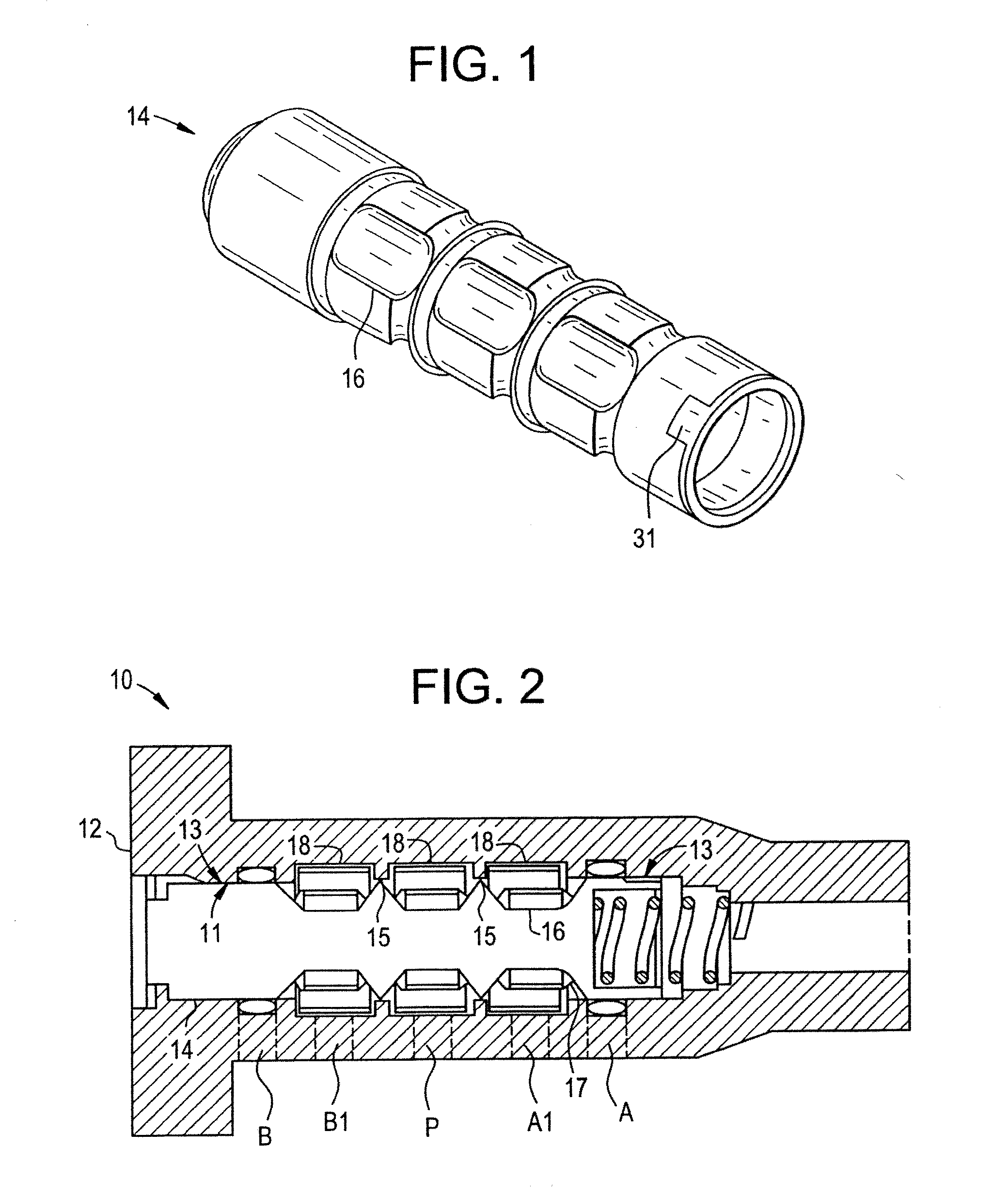
[0027]The perspective view of FIG. 1 illustrates a spool 14 for use with a hydraulic valve 10 according to the invention. Such hydraulic valve 10 in turn may be adapted for use with a cam phasing apparatus (not depicted) of an internal combustion engine (not depicted).

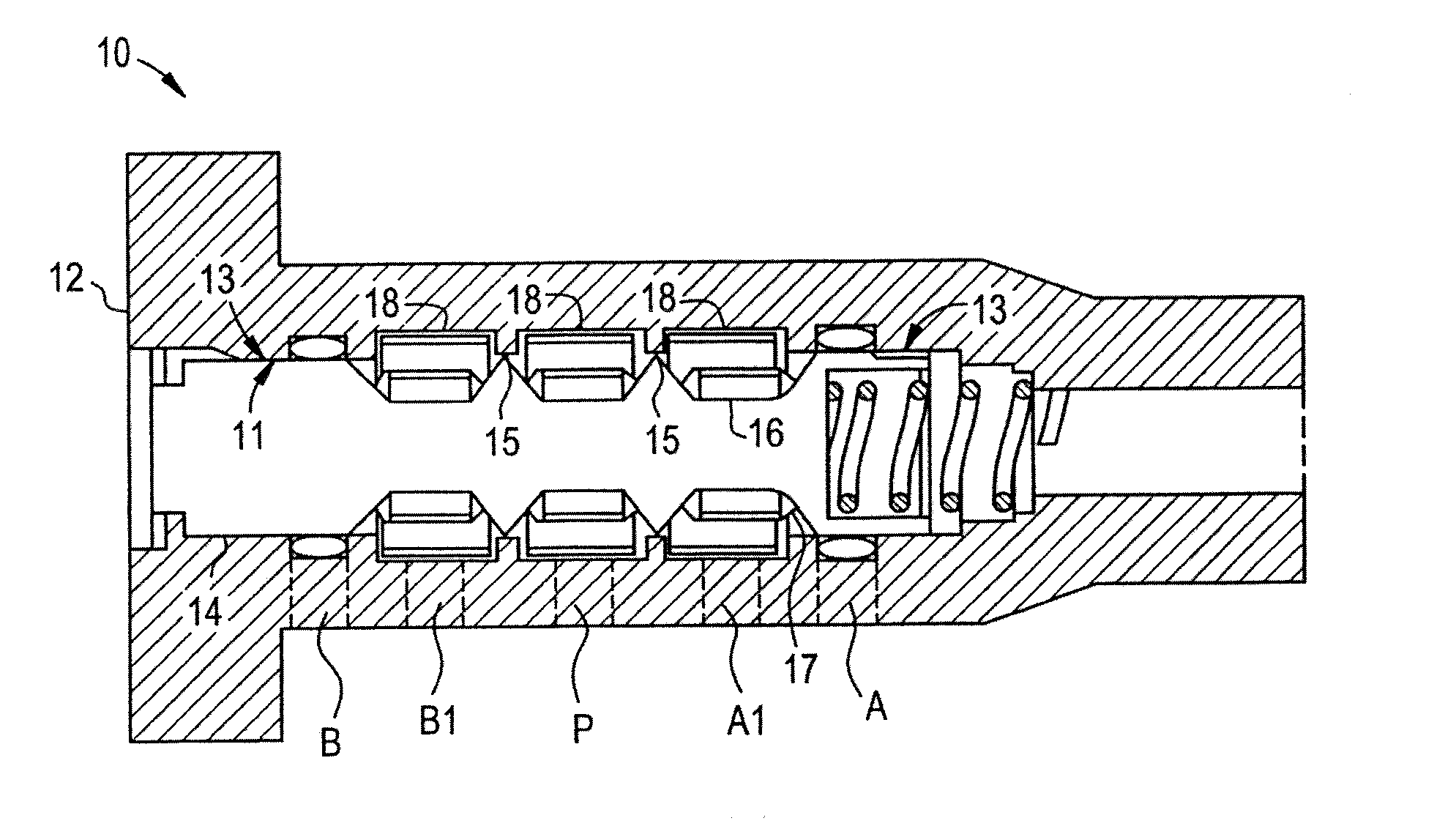
[0028]FIG. 2 is a cross-section of the hydraulic valve 10 in its entirety. As shown in this figure, the hydraulic valve 10 is essentially formed by a hollow bolt or snout 12 with the spool 14 being disposed coaxially inside the bolt 12. Bolt 12 has recessed pockets forming seats for check valve 18. The check valves allow flow into the bolt but restrict flow out. Herein, the bolt 12 and the spool 14 are configured such that the spool 14, while still being able to shift axially, is essentially captive inside the bolt 12. The relative geometry of the bolt 12 and the spool 14 thus allows for a certain degree of translational displacement of the spool 14 within the bolt 12.

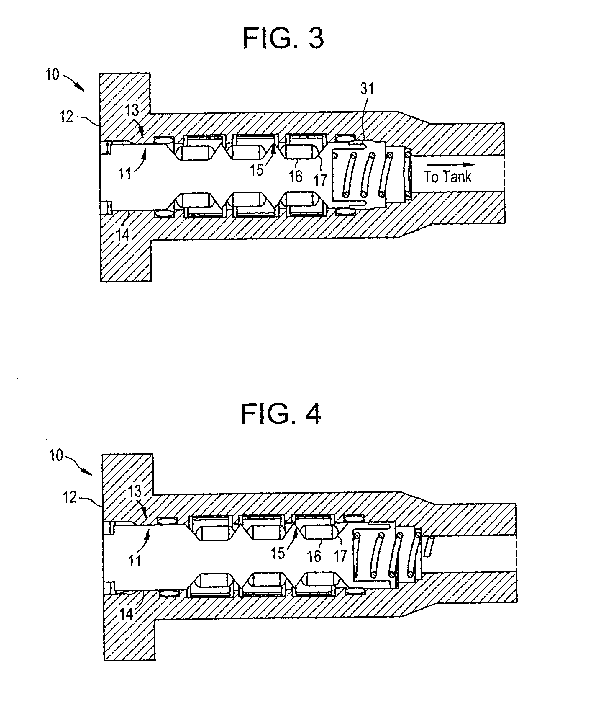
[0029]Depending on this translational displacement,...

sixth embodiment

[0037]FIG. 9 to FIG. 12 each refer to the invention. A hydraulic valve 60 according to this embodiment is characterized by an essentially tubular cartridge 68 for holding the spool 64, the cartridge 68 in turn being disposed inside the bolt 62. The check valves 63 are placed around the cartridge but inside the bolt. The check valve compression is limited to the cartridge outside diameter. When being shifted, the spool 64 thus effectively rides on the inside of the cartridge 68, the latter forming a physical barrier separating the check valves 63 and the spool 64.

[0038]Owing to its fairly complex geometry, FIG. 9 and FIG. 10 show two views of the cartridge 68 from different perspectives. Similarly, FIG. 11 and FIG. 12 provide cross-sections of the complete hydraulic valve 60 in two orthogonal planes to elucidate its design.

seventh embodiment

[0039]FIG. 13 is a partial view of a hydraulic valve 70 according to a In addition to the bolt 72 and spool 74, this hydraulic valve 70 comprises three or more circumferential stops 79 installed inside the bolt 72, each stop 79 protruding toward the longitudinal axis of the spool 74 to limit compression of the check valves 75. Preferably, the stops 79 are configured to prevent any contact of the spool 74 with the check valves 75. The stops 79 are headless screws screwed into radial threaded holes in the bolt 72. The inner ends of the stops 79 are shaped like a pin 102 protruding towards the longitudinal axis of the spool 74.

[0040]FIG. 15 shows an orthogonal cross section of the hydraulic valve 70. As long as the check valves 75 closes the hole establishing the supply port P, it covers this hole. In this state, the diameter of the band check valve 75 is at its maximum. In a circumferential position, the end faces 105, 106 of the band check valve 75 are distanced with clearances 101,...


PUM


Abstract

In a hydraulic valve comprising a spool, one or more band-shape check valves and an enclosing bolt or snout, the check valve may be compressed to the point of excessive wear or failure and may impede spool movement. The problem outlined is solved by an inventive hydraulic valve for use with a cam phasing apparatus of an internal combustion engine. The hydraulic valve comprises a hollow bolt or snout, check valves, and a spool disposed inside the bolt while still being able to shift axially within the bolt. The bolt and spool are configured to provide fluid passageways between the spool and the cam phasing apparatus depending on a translational displacement of the spool. Furthermore, the spool is configured to allow an oil flow through the fluid passageway, yet limit a compression of the band-type check valves.

Description

[0001]TECHNICAL FIELD[0002]The present invention relates to hydraulic valve, and particularly to an oil control valve for variable camshaft timing in an internal combustion engine.BACKGROUND ART[0003]In the context of internal combustion engines (ICEs), the technique of altering the timing of a valve lift event is commonly referred to as variable valve timing (VVT). Use of such design is known in the art in order to, inter alia, improve upon the performance, fuel economy, or reduce the emissions of an internal combustion engine to which it is applied. Especially in the automotive industry, increasingly strict environmental regulations are causing countless manufacturers to modify the relative timing, duration, or opening of their engines' inlet and exhaust valves.[0004]Among several approaches to variable valve timing known to the skilled person, so-called cam phasing allows to change the phase of the camshaft's and valves' periodic movement. To this end, the camshaft is rotated rel...

Claims


Application Information

Patent Timeline
Patent Type & Authority Applications(United States)
IPC IPC(8): F01L9/02F01L1/344F01L1/04F16K11/085F16K15/02F01L9/14
CPCF01L9/025F16K11/0856F01L1/3442F01L1/04F16K15/026F16K11/07F01L2001/34426F01L2001/34433F16K15/142F01L9/14F16K15/1825
Inventor PARKER, KENNETH J.SNYDER, JOHNSAPP, BRIANDIEDERICHS, UDOKOENIG, MELISSA MEI
Owner HILITE GERMANY
Why Eureka
Try Eureka