Apparatus for generating a vortex for a vacuum cleaner

a vacuum cleaner and apparatus technology, applied in the direction of machines/engines, liquid fuel engines, cleaning filter means, etc., can solve the problems of noisy cyclonic vacuum cleaners and user's inability to control the movement of particulates inside the collection vessel

Active Publication Date: 2015-12-24
SAMSUNG ELECTRONICS CO LTD
View PDF6 Cites 1 Cited by
  • Summary
  • Abstract
  • Description
  • Claims
  • Application Information

AI Technical Summary

Benefits of technology

[0030]The support member may have a central aperture, and further comprise a filter above the central aperture arranged to remove dust par...

Problems solved by technology

As a result of the power required to generate the high speed airflow into the collection vessel, cyclonic vacuum cl...

Method used


Image

  • Apparatus for generating a vortex for a vacuum cleaner
  • Apparatus for generating a vortex for a vacuum cleaner
  • Apparatus for generating a vortex for a vacuum cleaner

Examples


Embodiment Construction

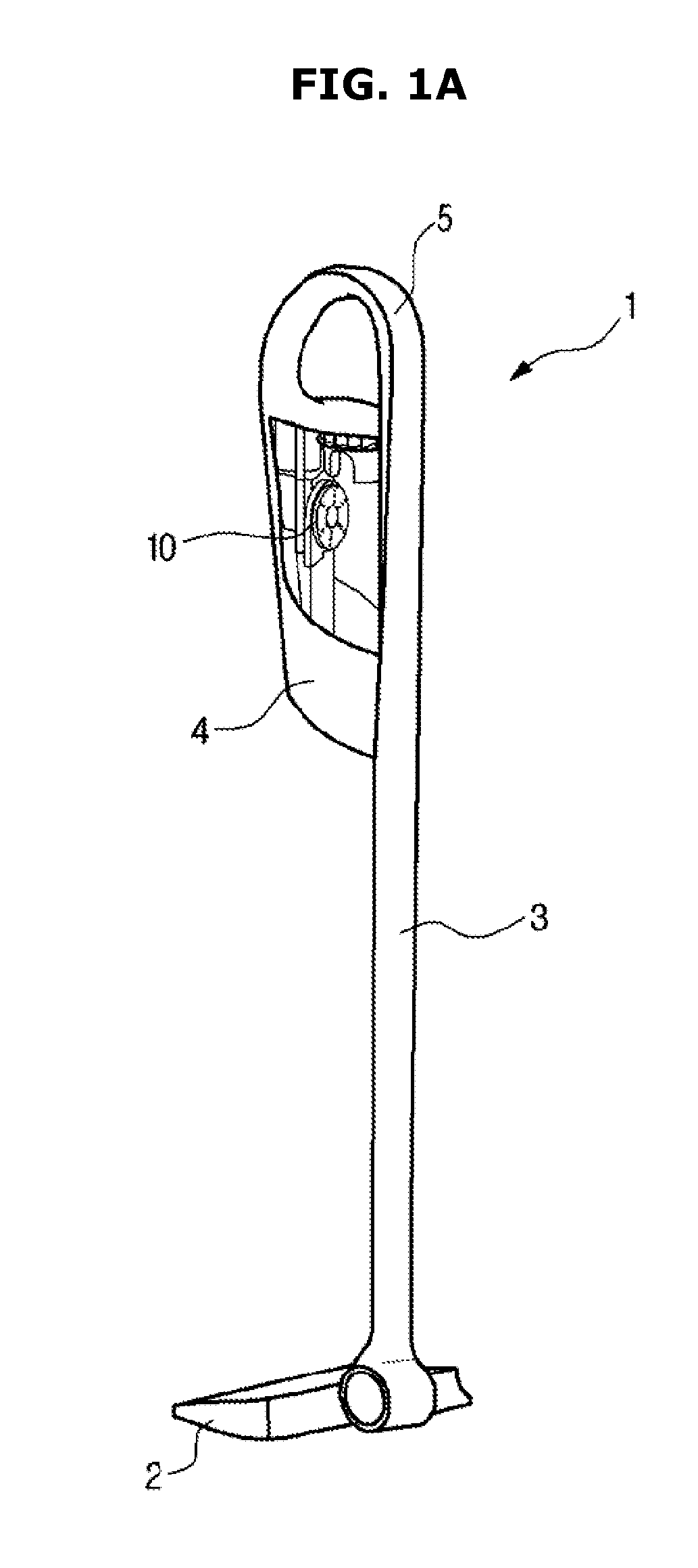
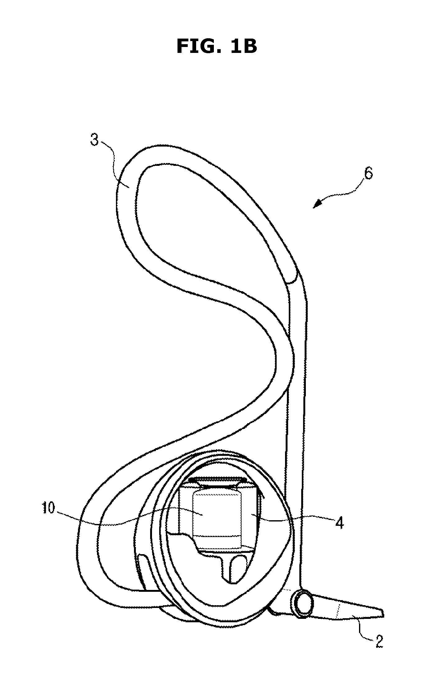
[0042]FIGS. 1A and 1B illustrate two common types of vacuum cleaner, being an upright cleaner and a canister (or cylinder) cleaner. The invention is not however limited to use in these types of vacuum cleaner, but can be implemented in any type of vacuum cleaner that uses the principle of cyclonic separation.

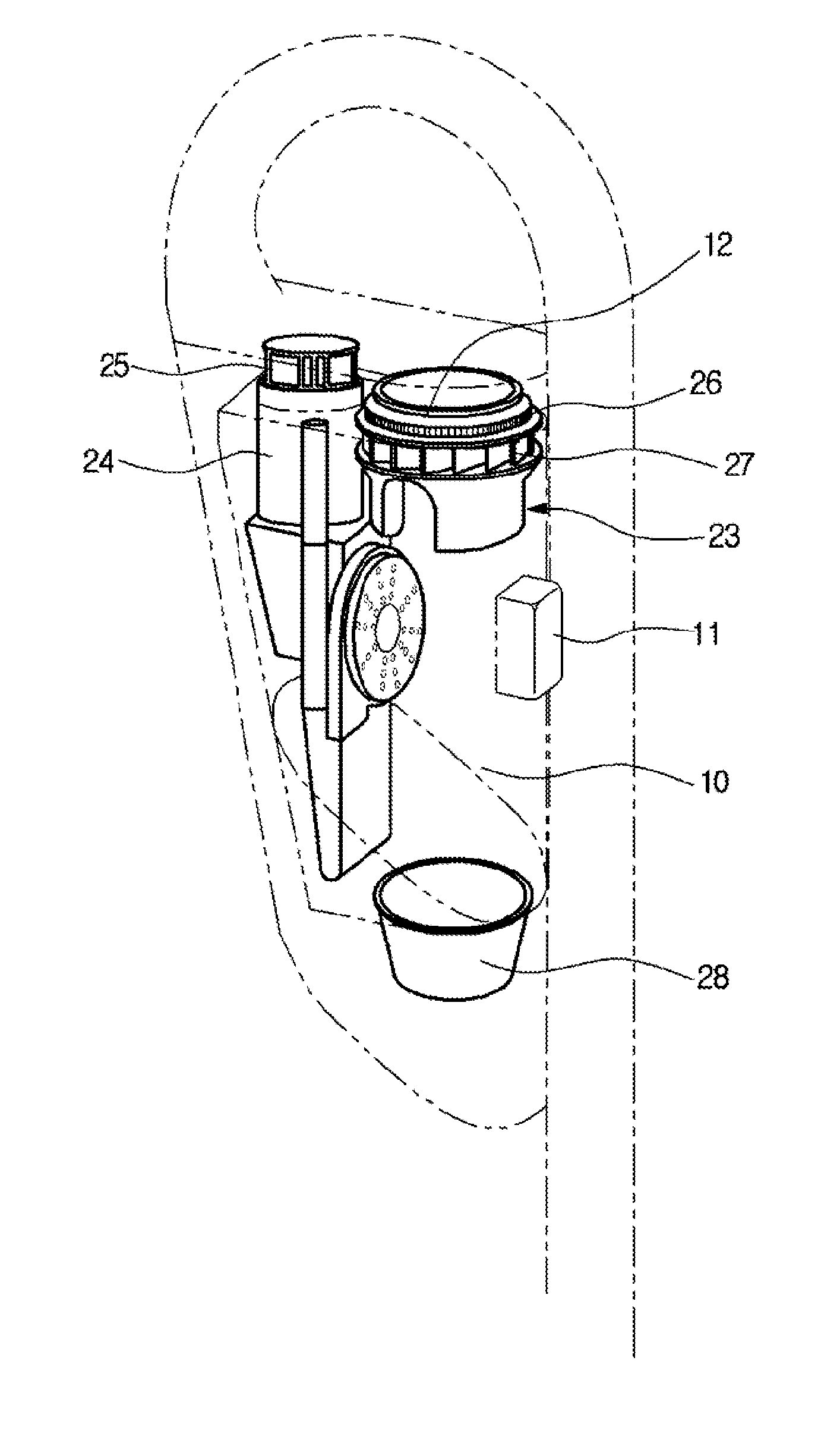
[0043]Referring to FIG. 1A, an upright vacuum cleaner 1 has a cleaning head 2, a tube or hose 3 connecting the cleaning head to a housing 4, and a handle 5. Air enters the vacuum cleaner 1 through the cleaning head 2 and travels up the tube 3 into a collection vessel 10 mounted within the housing 4. The suction required to draw air into the vacuum cleaner 1 is created inside the housing 4 by a vortex generating assembly, which will be described in more detail below.

[0044]In another embodiment shown in FIG. 1B, a canister vacuum cleaner 6 comprises a cleaning head 2, a hose 3 and a housing 4. As in the vacuum cleaner 1 shown in FIG. 1A, air enters the vacuum cleaner 6 through the...


PUM


Abstract

An apparatus for generating a vortex in a collection vessel of a vacuum cleaner, using a blade assembly rotatably mountable in the collection vessel. By rotating the blade assembly, a vortex is generated inside the collection vessel, and enough suction is created to draw air through the entire system. The use of a blade assembly to generate the vortex may remove the need for an impeller external to the collection vessel, as the blade assembly may be capable of creating enough suction to draw air into the collection vessel. This may allow the vacuum cleaner to operate with lower noise.

Description

CROSS-REFERENCE TO RELATED APPLICATIONS[0001]This application claims the benefit of UK Patent Application No. 1410884.9, filed on Jun. 18, 2014 in the UK Intellectual Property Office, the disclosure of which is incorporated herein by reference.BACKGROUND[0002]1. Field[0003]The present invention relates to an apparatus for generating a vortex, for use in a vacuum cleaner.[0004]2. Description of the Related Art[0005]Many types of vacuum cleaner are currently commercially available, including upright vacuum cleaners and canister (also known as cylinder) vacuum cleaners. These vacuum cleaners can be broadly divided into two categories—those with a dust collection bag and those without a dust collection bag, often referred to as bagless vacuum cleaners.[0006]There has been considerable interest in bagless vacuum cleaners in recent years due to their potential advantages. For example, the suction in bagless vacuum cleaners is not reduced by build up of dust in a bag, and a user can see ho...

Claims


Application Information

Patent Timeline
IPC IPC(8): F04D29/36A47L5/28F04D19/00A47L9/16
CPCF04D29/362A47L9/1683F04D19/00A47L9/1666A47L5/28F04D17/16F04D29/36A47L9/16A47L9/1608A47L5/22A47L9/1675F04D29/287B04C5/185A47L9/1658A47L9/0072
Inventor LEE, KYUNG HOON
Owner SAMSUNG ELECTRONICS CO LTD
Why Eureka
Try Eureka