Diaphragm valve with dual point seal and floating diaphragm web

Active Publication Date: 2015-12-24
PARKER INTANGIBLES LLC
View PDF12 Cites 10 Cited by
  • Summary
  • Abstract
  • Description
  • Claims
  • Application Information

AI Technical Summary

Benefits of technology

[0006]In view of the deficiencies of conventional high purity diaphragm valves, a need exists in the art for an improved diaphragm valve having enhanced valve life, reliability, and performance. The present invention is a high purity valve having enhanced valve life and performance due to a configuration that significantly improves sealing by the diaphrag

Problems solved by technology

In addition, through the numerous cycles of operation, valve seat wear can occur, which reduces the efficacy of the seal.
The lack of an effective seal can reduce valve performance in conventional configurations.
A thin diaphragm web, however

Method used


Image

  • Diaphragm valve with dual point seal and floating diaphragm web
  • Diaphragm valve with dual point seal and floating diaphragm web
  • Diaphragm valve with dual point seal and floating diaphragm web

Examples


Embodiment Construction

[0019]Embodiments of the present invention will now be described with reference to the drawings, wherein like reference numerals are used to refer to like elements throughout. It will be understood that the figures are not necessarily to scale.

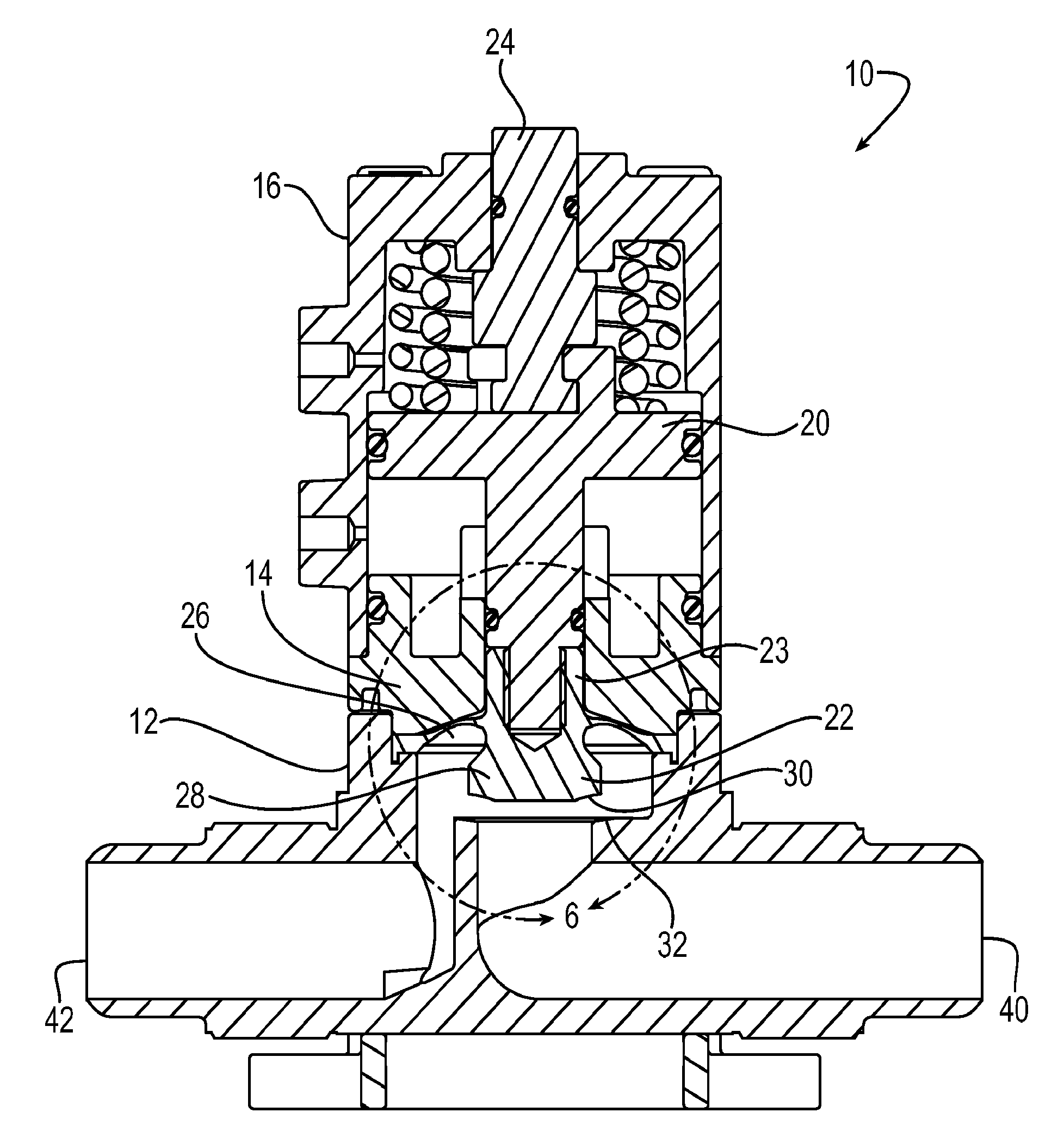
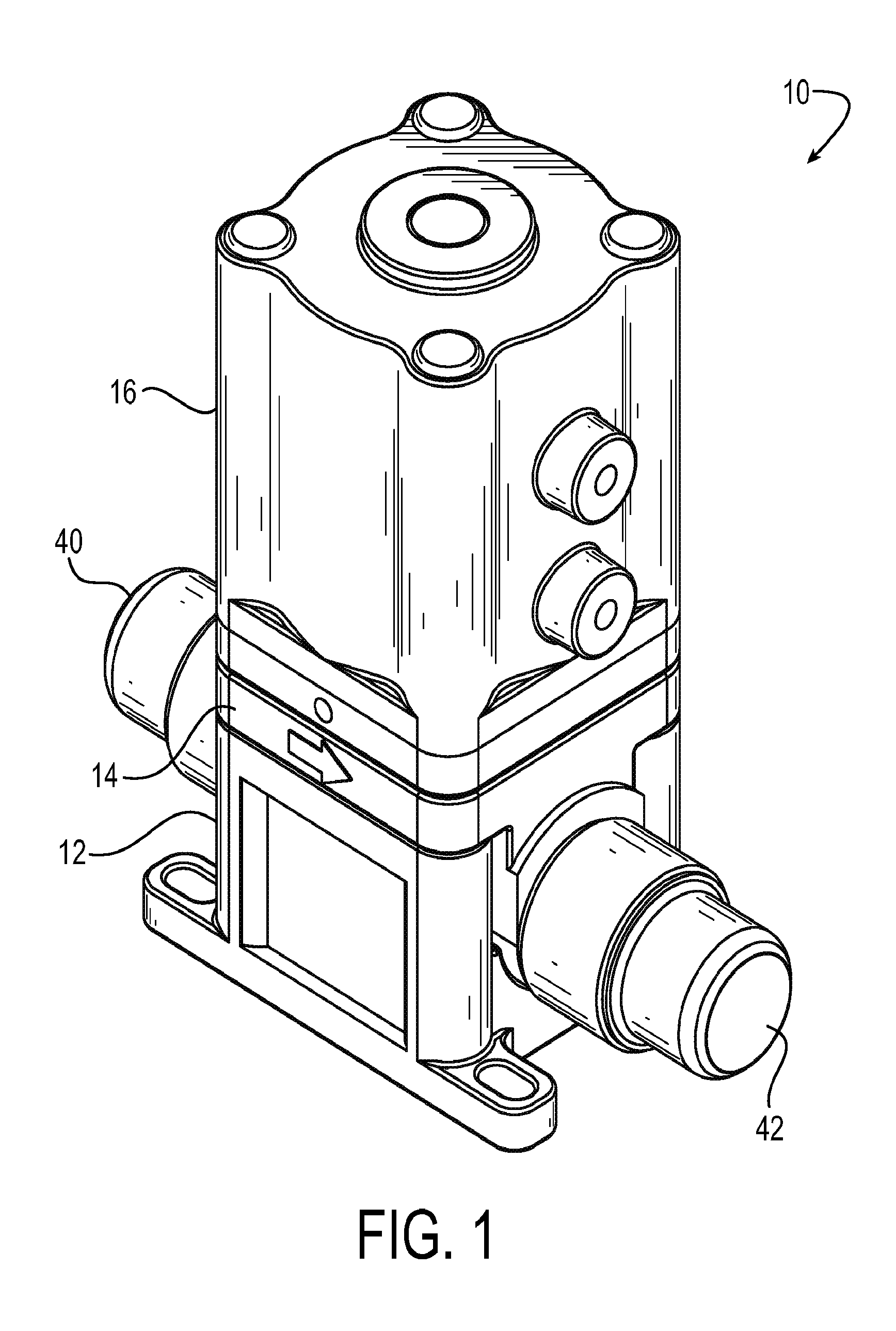
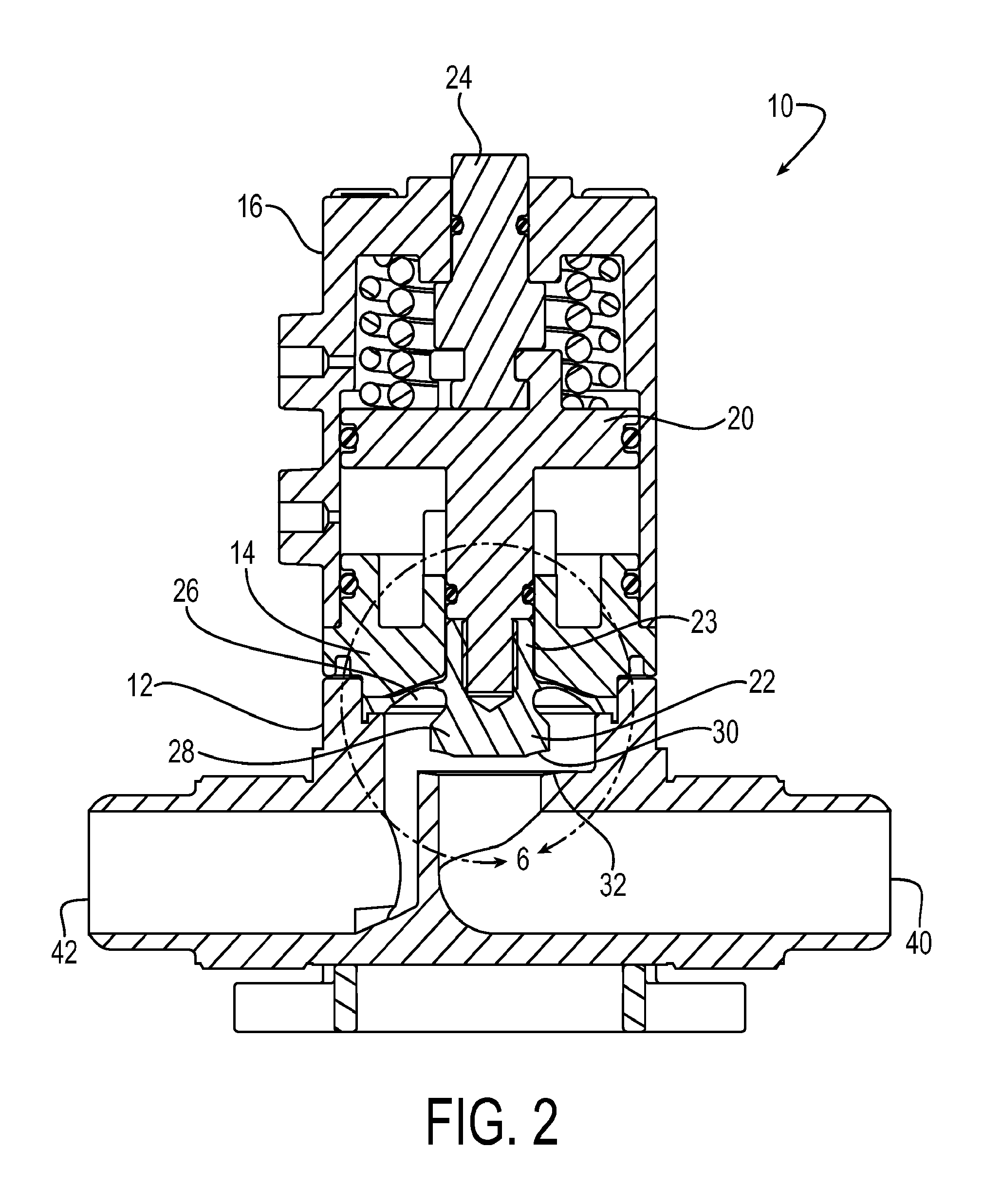
[0020]FIG. 1 is a schematic diagram that depicts an isometric view of an exemplary high purity valve 10 in accordance with embodiments of the present invention. FIG. 2 is a schematic diagram that depicts a side cross-sectional view of the exemplary high purity valve 10 of FIG. 1, with the valve in the open position. FIG. 3 is a schematic diagram that depicts a side cross-sectional view of the exemplary high purity valve 10 of FIG. 1, with the valve in the closed position.

[0021]Referring to FIGS. 1-3, the valve 10 includes a valve body 12, a retainer 14, and a housing 16 that are coupled to one another. The housing 16 encloses the valve body 12. Referring more specifically to the cross-sectional views of FIGS. 2-3, the housing 16 encloses a pis...


PUM


Abstract

A high purity valve (10) includes a valve body (12) having an inlet (40) and an outlet (42) separated by a valve seat (32), and a diaphragm (22) having a central stem (23) that has a first end coupled to a piston (20) for actuating the valve, and a poppet (28) for engaging the valve seat to close the valve. The poppet forms a dual point seal (50/52, 50′/52′) with the valve seat having at least two points of contact between an annular surface (30) of the poppet and the valve seat. The annular surface of the poppet may be either a concave surface or a convex surface that provides the dual point seal. The valve has a retainer (14) adjacent the diaphragm, and the diaphragm has a flexible web (26) that extends radially outward from the central stem. The retainer has a surface (60) adjacent the web, and the surface is spaced apart from the web such that the web does not contact the surface when the valve is pressurized.

Description

RELATED APPLICATIONS[0001]This application claims the benefit of U.S. Provisional Application Nos. 61 / 769,467 and 61 / 769,519, both filed on Feb. 26, 2013, which are incorporated herein by reference.FIELD OF INVENTION[0002]The present application relates generally to diaphragm valves, and more particularly, to fluoropolymer valves for use in high purity systems, such as semiconductor manufacturing or other corrosive or high purity applications.BACKGROUND[0003]Various high purity systems, such as systems for manufacturing pharmaceuticals, semiconductors, and the like, use high purity diaphragm valves, such as valves made from fluoropolymers. Typical high purity valves have a valve body with an inlet and an outlet separated by a valve seat and a diaphragm. The diaphragm typically has a central stem for sealing against the valve seat to open and close the valve, and an outwardly extending web that seals the cavity of the valve. One existing valve for such a system includes a tongue and ...

Claims


Application Information

Patent Timeline
IPC IPC(8): F16K7/17F16K31/126F16K41/10
CPCF16K7/17Y10T137/7781F16K31/126F16K41/103F16K1/34F16K1/36F16K1/38
Inventor SMITH, ZACHARY SPENCERCONNER, DARREN EDWARD
Owner PARKER INTANGIBLES LLC
Why Eureka
Try Eureka