Magnetic absolute rotary encoder

a rotary encoder and absolute magnetic technology, applied in the field of rotary encoders, can solve the problems of high cost, high cost, and high cost of electrical contact encoders, and achieve the effects of improving accuracy, reducing cost, and simple operation

Active Publication Date: 2015-12-24
MULTIDIMENSION TECH CO LTD
View PDF5 Cites 7 Cited by
  • Summary
  • Abstract
  • Description
  • Claims
  • Application Information

AI Technical Summary

Benefits of technology

[0028]According to the present invention, a magnetic rotary encoder wi

Problems solved by technology

Optical methods suffer from problems from dirt and light pollution, and high expense due to needed electronic components for both light source and light detector.
Electrical contact encoders suf

Method used


Image

  • Magnetic absolute rotary encoder
  • Magnetic absolute rotary encoder
  • Magnetic absolute rotary encoder

Examples


example 1

[0045]A first example of a preferred embodiment of the present invention, has one permanent magnet for each coding unit.

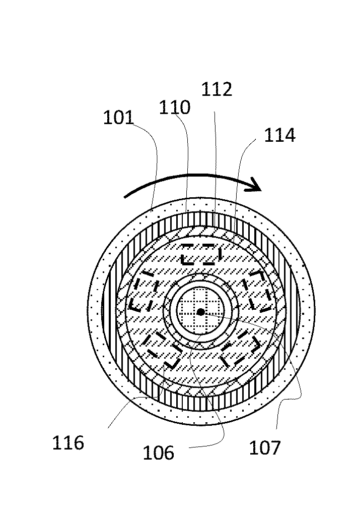
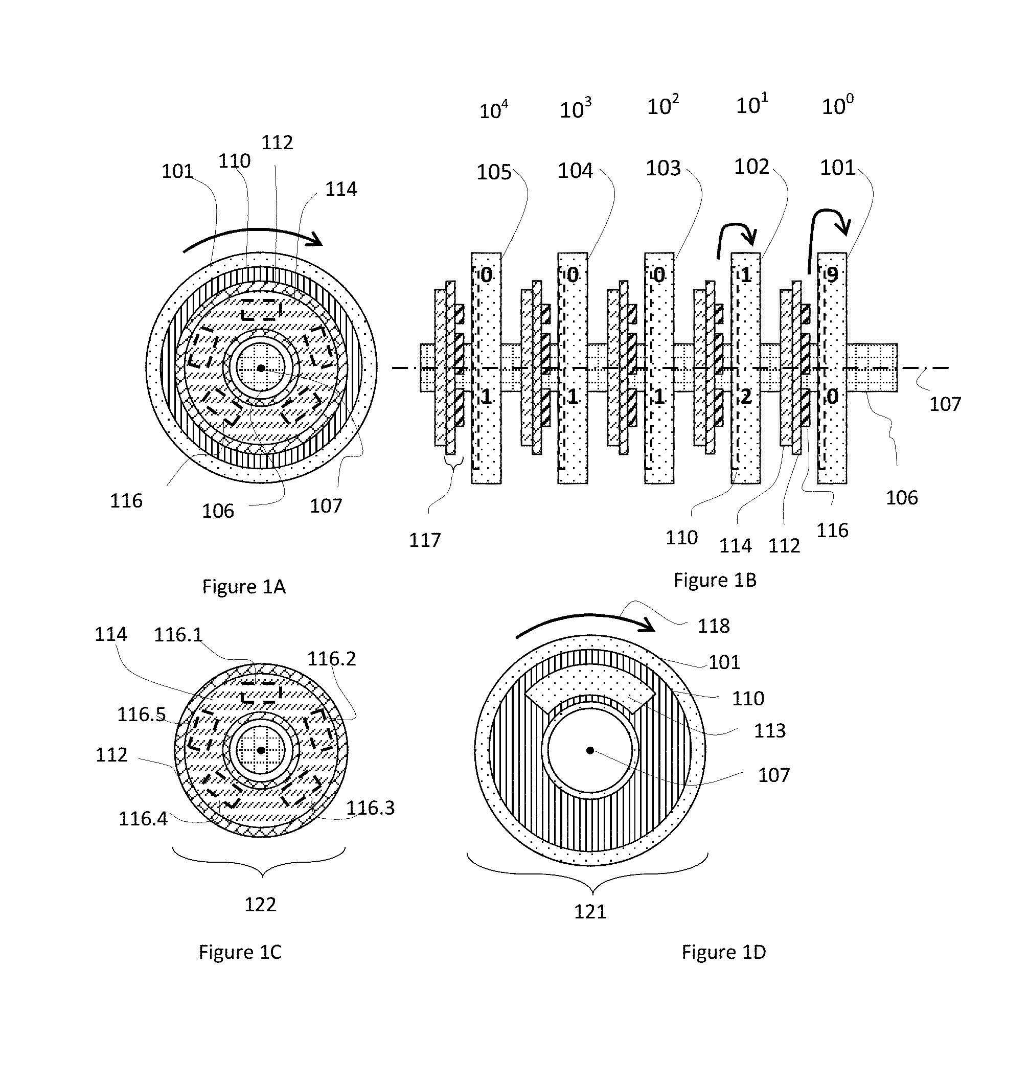
[0046]As shown in FIG. 1, each rotor has a permanent magnet count corresponding thereto, i.e. each encoding unit corresponds to the permanent magnet. FIG. 1A shows an end-on view of the five wheels illustrated on the right side as FIG. 1B which shows a side view of the rotary encoder device 100. In order to more easily see the two parts of the wheel, the wheel is broken into two parts illustrated in FIGS. 1C and 1D. In this embodiment, the piece shown in FIG. 1C is a the fixed portion, and that shown in FIG. 1D is a rotating portion. All of the wheels 101, 102, . . . , 105 rotate on shaft 106 whose axis is co-axial with the axis of rotation 107. Magnetically permeable disk 110 is mounted on wheel 101 so that the permeable disk 110 and wheel 101 rotate together about axis 107. Magnet 114 is mounted in a way that is does not rotate, but rather is fixed to an external...

example 2

[0048]Magnetic rotary encoder preferred implementation example 2 provides a permanent magnet that is shared by two wheels.

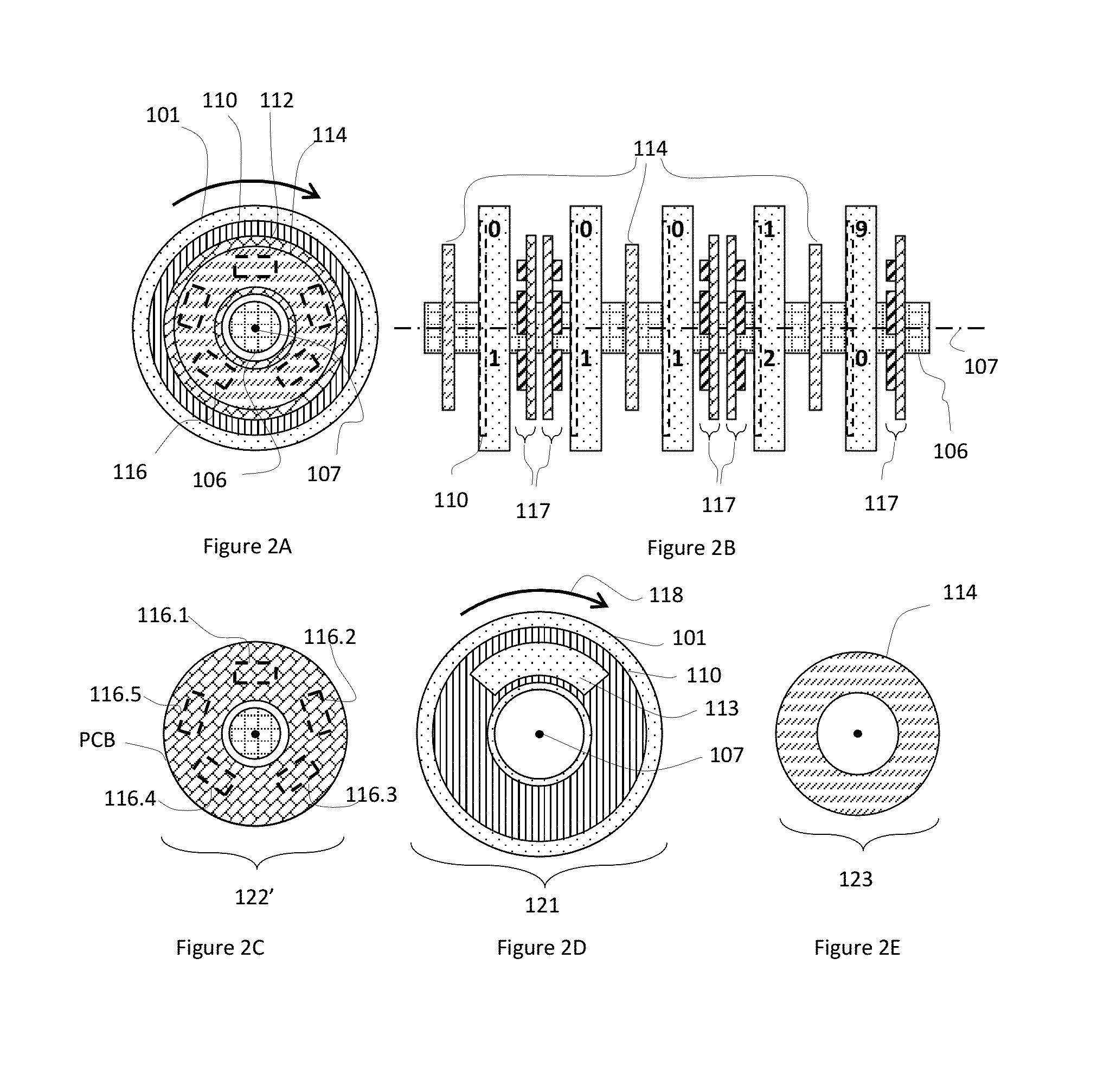
[0049]A different arrangement of fixed magnets 114 is shown in FIG. 2. The upper left part of FIG. 2 shows an end on view of the 5-wheel assembly whose side view is in the upper right. The end-on view is broken into three parts in the lower half of FIG. 2 in order to more easily see the parts of the wheel clearly. The lower left and lower right of FIG. 2 have the two portions of the wheel that are fixed, and the lower center has the portion that rotates. Here, the fields from one of magnets 114 are detected by two sensor assemblies 117. This saves space and cost in a multi-wheel assembly. In this arrangement, magnet 114 is the only component of a separate fixed assembly 123. Rotating assembly 121 is constructed the same as in FIG. 1. The sensor assemblies 117 form fixed assembly 122′.

[0050]In a multi-wheel magnetic rotary encoder, the arrangement used in this emb...

example 3

[0052]Magnetic rotary encoder preferred implementation example 3 provides a magnet is located on the wheel, and the encoder disk can be rotated together with the rotor about a rotation axis, and the sensor unit comprises five sensors, as shown in FIG. 3.

[0053]FIG. 3A is a right side view of a coding unit, and FIG. 3B is a cross-sectional view taken along the direction A in FIG. 3A. PCB 112 is drawn in outline only at left in order to enable a clearer view of the other components. In this arrangement, magnet 114 is placed on wheel 101 in very close proximity to, or touching, disk 110; these components rotate together about the axis 107. PCB 112 is shown as a rectangular form in FIG. 3. If designed with a mechanical connection means, PCB 112 can serve the purpose of structural support for the wheel assembly in addition to providing electrical connections for sensors 116.1-116.5.

[0054]The active elements in sensors 116 are present near the surface furthest away from the PCB 112. They a...


PUM


Abstract

Provided is a magnetic absolute rotary encoder, comprising a rotation shaft, multiple rotating wheels that can rotate along the rotation shaft, multiple encoding units that correspond to the multiple rotating wheels one-to-one, and one or more permanent magnet assemblies that provide the magnetic bias to the multiple encoding units. Each encoding unit comprises a magnetically permeable encoder disc, the structure thereof enabling the magnetic permeability thereof to be different according to the different positions of the rotation shaft, and comprises multiple sensor units that comprise multiple magnetic sensors. The sensor units are used to sense the magnetic permeability of the magnetically permeable encoder disc and to output the sensor signals that characterize the relative position of the magnetically permeable encoder disc. According to the sensor signals of the sensor units, each encoding unit outputs the value that characterizes the selected rotation position of the corresponding rotation wheel, thereby enabling an absolute magnetic rotating encoder that is simple and low in cost and has more precise magnetic encoder discs.

Description

TECHNICAL FIELD[0001]The present invention relates to a rotary encoder. More particularly, the present invention relates to an improved absolute magnetic rotary encoder.BACKGROUND OF THE INVENTION[0002]Existing encoders may be used in automatic utility meter reading or any application where total flow must be monitored at remote locations over long time periods. They can be included in any device that utilizes rotating wheels to measure cumulative flow of gas or liquid. In these meters, the total number of rotations of the wheels is indicative of the total flow through the meter. Common encoders involving optical, electrical contacts, or inductive mechanisms may be used. Absolute rotary encoders are a subset of rotary encoders, which provide information about the rotational position of each reel at any time, without the need to monitor and count pulses caused by the movement of the wheel. These encoders typically include a rotating wheel and provide an appropriate output of the whee...

Claims


Application Information

Patent Timeline
IPC IPC(8): G01D5/12G01B7/30
CPCG01B7/30G01D5/12G01F15/066G01D5/2497G01D5/2515G01D5/145G01D5/147G01R11/16G01D2205/26
Inventor DEAK, JAMES GEZAWEI, JILIELIU, JINGFENG
Owner MULTIDIMENSION TECH CO LTD
Why Eureka
Try Eureka