Cross-Sensor Standardization

a technology of cross-sensors and sensors, applied in the direction of instruments, optical radiation measurement, borehole/well accessories, etc., can solve the problems of affecting the way instrument standardization is performed, and the cost associated with fluid prediction model development and managemen

Inactive Publication Date: 2015-12-24
HALLIBURTON ENERGY SERVICES INC
View PDF2 Cites 10 Cited by
  • Summary
  • Abstract
  • Description
  • Claims
  • Application Information

AI Technical Summary

Problems solved by technology

The costs associated with fluid prediction model development and management affects how instrument standardization is performed.

Method used


Image

  • Cross-Sensor Standardization
  • Cross-Sensor Standardization
  • Cross-Sensor Standardization

Examples


example one

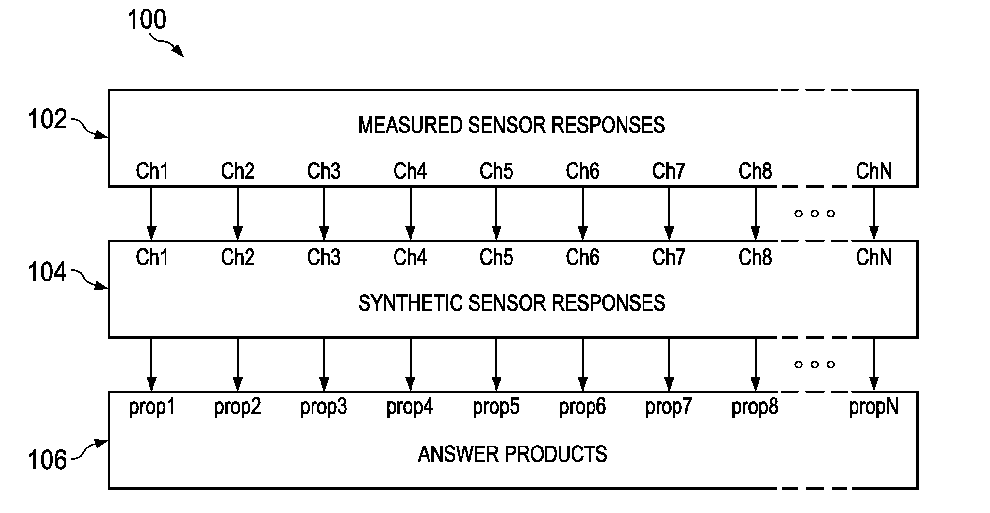
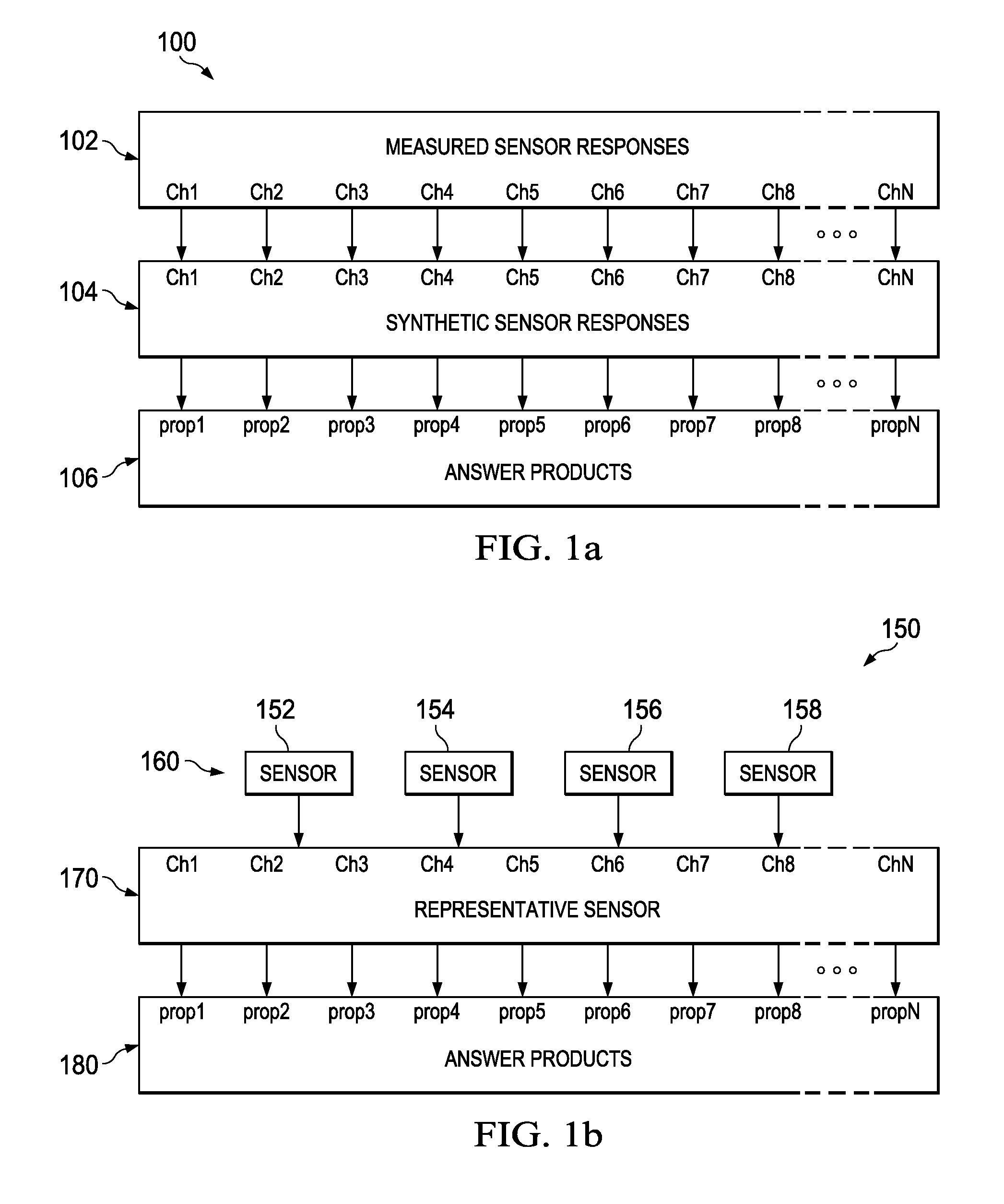
[0046]A computer-implemented method for generating a cross-sensor standardization model, the method comprising selecting a representative sensor from a group of sensors comprising at least one of same primary optical elements and similar synthetic optical responses; and calibrating the cross-sensor standardization model based on a matched data pair for each sensor in the group of sensors and for the representative sensor.

example two

[0047]A computer-implemented method for generating a cross-sensor standardization model, the method comprising selecting a representative sensor from a group of sensors comprising at least one of same primary optical elements and similar synthetic optical responses; calibrating the cross-sensor standardization model based on a matched data pair for each sensor in the group of sensors and for the representative sensor; and generating the matched data pair, wherein the matched data pair comprises calibration input data and calibration output data.

example three

[0048]A computer-implemented method for generating a cross-sensor standardization model, the method comprising selecting a representative sensor from a group of sensors comprising at least one of same primary optical elements and similar synthetic optical responses; calibrating the cross-sensor standardization model based on a matched data pair for each sensor in the group of sensors and for the representative sensor; and identifying each sensor to form the group of sensors, wherein each sensor comprises at least one of the same primary optical elements and the similar synthetic optical responses.


PUM


Abstract

The disclosed embodiments include a method, apparatus, and computer program product for generating a cross-sensor standardization model. For example, one disclosed embodiment includes a system that includes at least one processor; at least one memory coupled to the at least one processor and storing instructions that when executed by the at least one processor performs operations comprising selecting a representative sensor from a group of sensors comprising at least one of same primary optical elements and similar synthetic optical responses and calibrating a cross-sensor standardization model based on a matched data pair for each sensor in the group of sensors and for the representative sensor. In one embodiment, the at least one memory coupled to the at least one processor and storing instructions that when executed by the at least one processor performs operations further comprises generating the matched data pair, wherein the matched data pair comprises calibration input data and calibration output data.

Description

BACKGROUND OF THE INVENTION[0001]Various multivariate models are used to predict chemical compositions and other properties of unknown reservoir fluid samples during formation fluid analysis that are based on the measurements of downhole optical tools. The application of pre-calibrated fluid prediction models is tool dependent, often requiring data standardization or transformation to convert measured sensor responses from the tool data space to the calibration data space. The costs associated with fluid prediction model development and management affects how instrument standardization is performed.BRIEF DESCRIPTION OF THE DRAWINGS[0002]Illustrative embodiments of the present invention are described in detail below with reference to the attached drawing figures, which are incorporated by reference herein and wherein:[0003]FIG. 1a illustrates an example data processing workflow for an individual sensor;[0004]FIG. 1b illustrates an example data processing workflow using multivariate m...

Claims


Application Information

Patent Timeline
Patent Type & Authority Applications(United States)
IPC IPC(8): G01J1/02G01D18/00
CPCG01D18/002G01J1/0295E21B41/00E21B47/135
Inventor CHEN, DINGDINGPERKINS, DAVID L.
Owner HALLIBURTON ENERGY SERVICES INC
Why Eureka
Try Eureka