Coil component and method of producing the same

a technology of coil components and coils, applied in the direction of transformers/inductances, magnets, magnetic bodies, etc., can solve the problems of difficult to accurately wind the wires at the same turn at the same time, long winding work time (takt time), and low magnetic coupling between the wires, so as to achieve excellent magnetic coupling and efficient production of high-performance coil components.

Inactive Publication Date: 2015-12-24
TDK CORPARATION
View PDF2 Cites 12 Cited by
  • Summary
  • Abstract
  • Description
  • Claims
  • Application Information

AI Technical Summary

Benefits of technology

[0013]According to the present invention, a method of producing a coil component in which a first wire and a second wire are wound around a winding core includes: winding a nth turn of the first wire and a nth turn of the second wire around a surface of the winding core in parallel and forming a first winding layer; winding each of n+1th and subsequent turns of the second wire except for at least a final turn on the surface of the winding core so as to be parallel to a previous turn of the second wire and forming the first winding layer together with the nth turn of the first wire and the nth turn of the second wire; and winding each of n+1th and subsequent turns of the first wire except for at least a final turn on the first winding layer so as to be fitted into a valley of the first winding layer formed by the same and previous turns of the second wire and forming a second winding layer. According to the present invention, it is possible to efficiently produce the high-performance coil component by using a well-known spindle winding machine.
[0014]According to the present invention, it is possible to provide a coil component that is excellent in the magnetic coupling between a pair of wires at the same turn and which is unlikely to face a collapse of the winding or an irregular winding, and a method of producing the coil component.

Problems solved by technology

The problem is that winding-work time (takt time), or the time required to completely wind the two wires, becomes long.
Therefore, the problem is that the magnetic coupling is low between the wires at the same turn.
Moreover, since the distance between the wires at the same turn is long, it is difficult to accurately wind the wires at the same turn at the same time.
Therefore, another problem is that a collapse of the winding or an irregular winding is likely to occur.

Method used


Image

  • Coil component and method of producing the same
  • Coil component and method of producing the same
  • Coil component and method of producing the same

Examples


Embodiment Construction

[0023]Preferred embodiment of the present invention will be described hereinafter in detail with reference to the accompanying drawings.

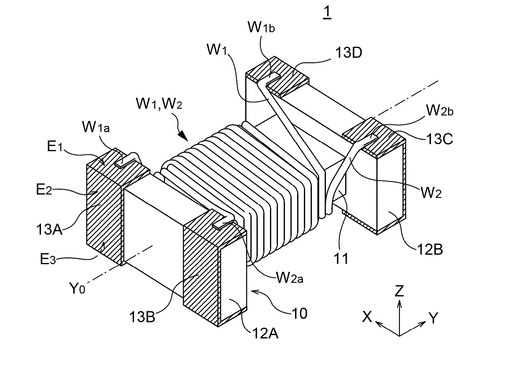
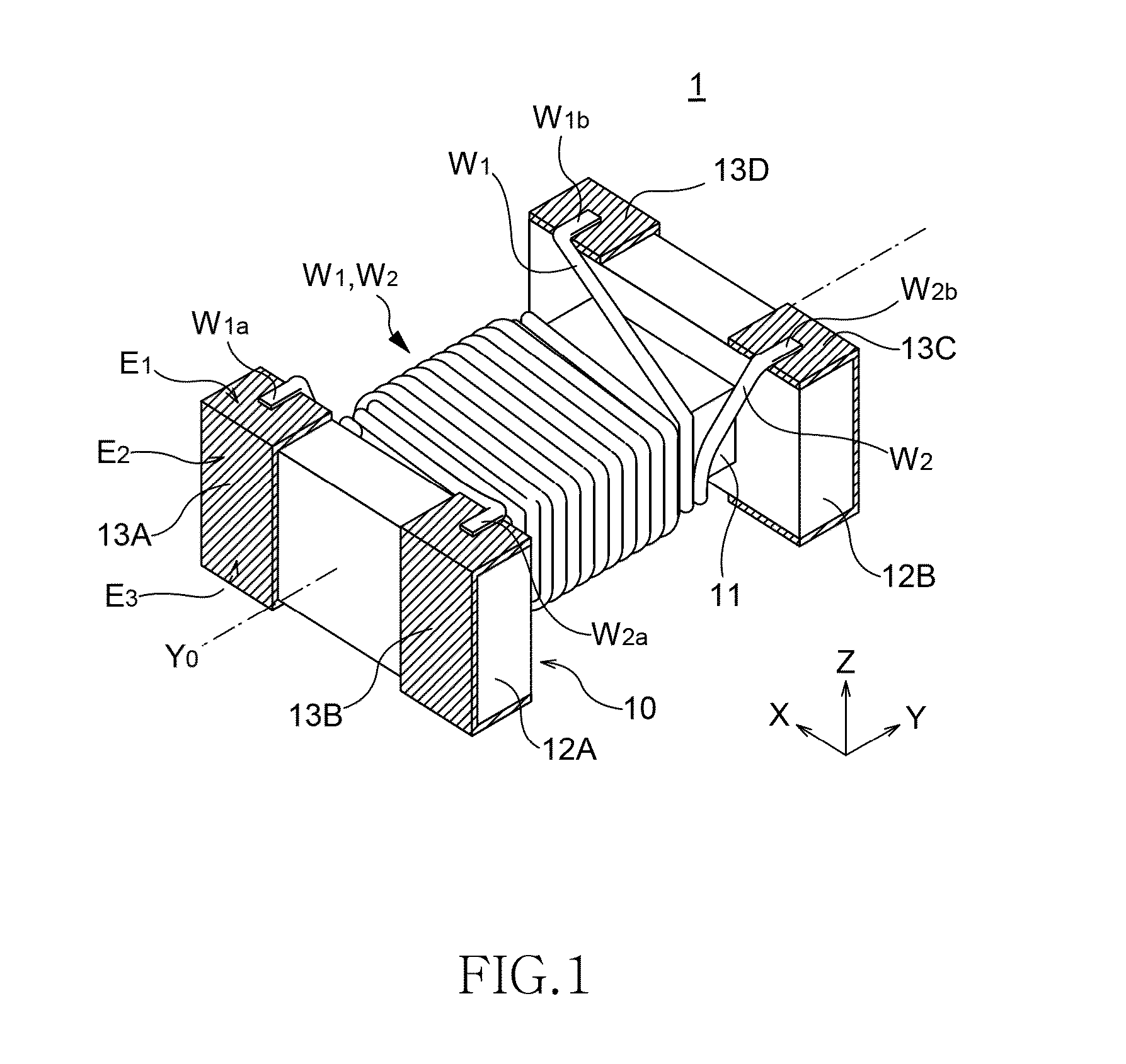
[0024]FIG. 1 is a perspective view of the appearance of a coil component 1 according to a preferred embodiment of the present invention.

[0025]As shown in FIG. 1, the coil component 1 includes a drum core 10, which is made from magnetic material; and a first wire W1 and a second wire W2, which are wound around the drum core 10.

[0026]The drum core 10 includes a rod-shaped winding core 11 and flanges 12A and 12B, which are provided at both ends of the winding core 11. The winding core 11 and the flanges 12A and 12B are integrally formed. The first wire W1 and the second wire W2 are wound around the winding core 11 of the drum core 10.

[0027]On one flange 12A of the drum core 10, a pair of terminal electrodes 13A and 13B is provided. On the other flange 12B, a pair of terminal electrodes 13C and 13D is provided. Among the pair of terminal electrodes 13A ...


PUM

PropertyMeasurementUnit
magneticaaaaaaaaaa
timeaaaaaaaaaa
distanceaaaaaaaaaa

Abstract

A coil component is provided with first wire and second wires that are wound around a winding core. nth turns of the first and second wires are wound around a surface of the winding core in this order in parallel and form a first winding layer. Each of n+1th and subsequent turns of the second wire is wound around the surface of the winding core so as to be parallel to a previous turn of the second wire and form the first winding layer. Each of n+1th and subsequent turns of the first wire is wound on the first winding layer so as to be fitted into a valley of the first winding layer formed by the same and previous turns of the second wire and form a second winding layer. The same turns of the first and second wires are adjacent to each other at each turn.

Description

BACKGROUND OF THE INVENTION[0001]1. Field of the Invention[0002]The present invention relates to a coil component and a method of producing the coil component, and particularly to a coil component that includes a winding structure in which two wires are wound around a winding core, as well as a method of producing the coil component.[0003]2. Description of Related Art[0004]Coil components, such as transformers, common mode filters, and baluns, have a pair of coils that are magnetically coupled to each other. In the case of a wire-wound coil component, two wires are wound around a magnetic core in order to form a pair of coils.[0005]As one type of the winding structure of the wire-wound coil component, a two-layer winding structure has been known. In a typical two-layer winding structure, at first one wire is wound around as a first layer. Then, on the first layer of the winding, a second-layer wire is wound. However, in the case of the typical two-layer winding structure, the second...

Claims


Application Information

Patent Timeline
Patent Type & Authority Applications(United States)
IPC IPC(8): H01F27/29H01F27/24H01F41/06H01F27/28
CPCH01F27/29H01F27/2823Y10T29/49073H01F41/0666H01F27/24H01F17/045H01F27/006H01F41/073
Inventor KAWASAKI, YOSHIHIROTAKAGI, NOBUOOHI, KOUYUABE, HIROYUKI
Owner TDK CORPARATION
Why Eureka
Try Eureka