
Knee orthosis for support of a knee joint

a knee joint and knee technology, applied in the field of knee joint support, can solve the problems of too large pressure and unoptimized pressure on the upper region of the lower leg, and achieve the effects of simple operation, good handling and simple manufactur

Active Publication Date: 2015-12-31
ORTHO TEAM
View PDF13 Cites 8 Cited by
  • Summary
  • Abstract
  • Description
  • Claims
  • Application Information

AI Technical Summary

Benefits of technology

The knee orthosis design helps provide stable support to the knee joint by keeping the cruciate ligament in the correct position. This helps in preventing the growth of tendon stumps and provides optimal stability in stretched and bent positions. The orthosis is made of a longitudinally stable, flexible element, such as a cable, which has good sliding characteristics and prevents soiling.

Problems solved by technology

It has thereby been shown that this pressure against the upper region of the lower leg is not optimal.
Thus, for example, this pressure can have the desired magnitude in the bent position of the knee, but in the stretched position of the knee this pressure is too great, which is disadvantageous.

Method used


Image

  • Knee orthosis for support of a knee joint
  • Knee orthosis for support of a knee joint
  • Knee orthosis for support of a knee joint

Examples


Embodiment Construction

[0034]Various embodiments of the present invention will now be described more fully hereinafter with reference to the accompanying drawings, in which some, but not all embodiments of the invention are shown. Indeed, embodiments of the invention may be embodied in many different forms and should not be construed as limited to the embodiments set forth herein. Rather, these embodiments are provided so that this disclosure will satisfy applicable legal requirements. Unless otherwise defined, all technical and scientific terms used herein have the same meaning as commonly known and understood by one of ordinary skill in the art to which the invention relates. The term “or” is used herein in both the alternative and conjunctive sense, unless otherwise indicated. Like numbers refer to like elements throughout.

[0035]Still further, to facilitate the understanding of this invention, a number of terms are defined below. Terms defined herein have meanings as commonly understood by a person of ...


PUM


Abstract

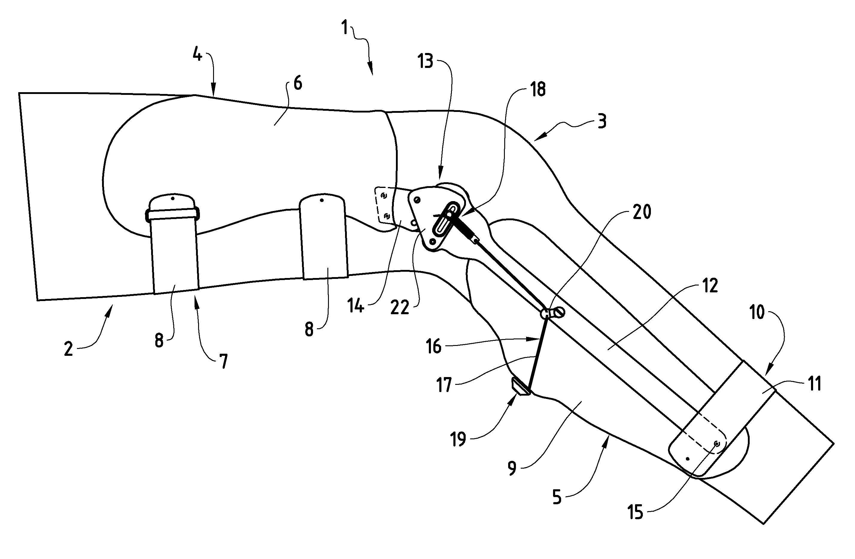
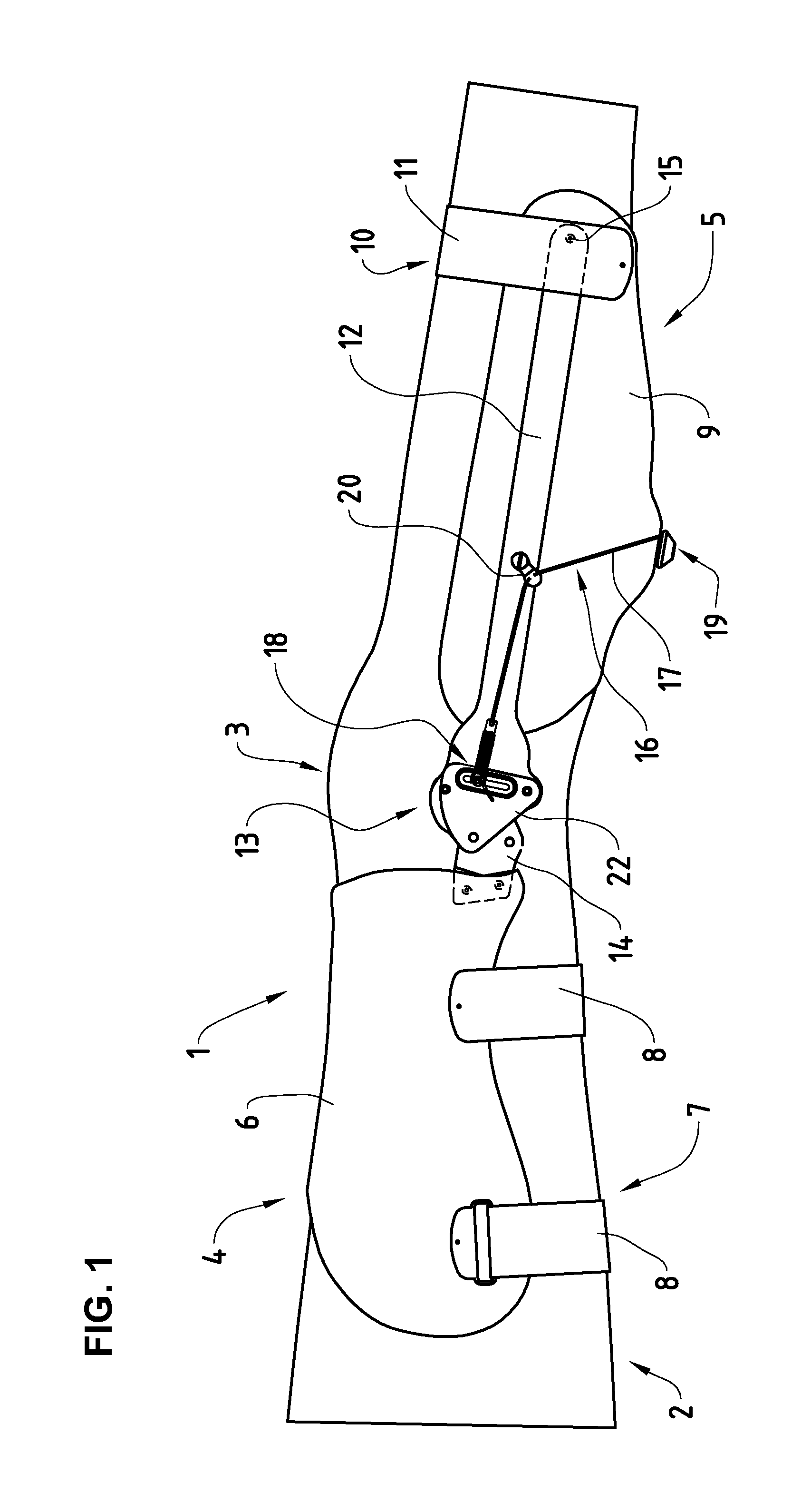
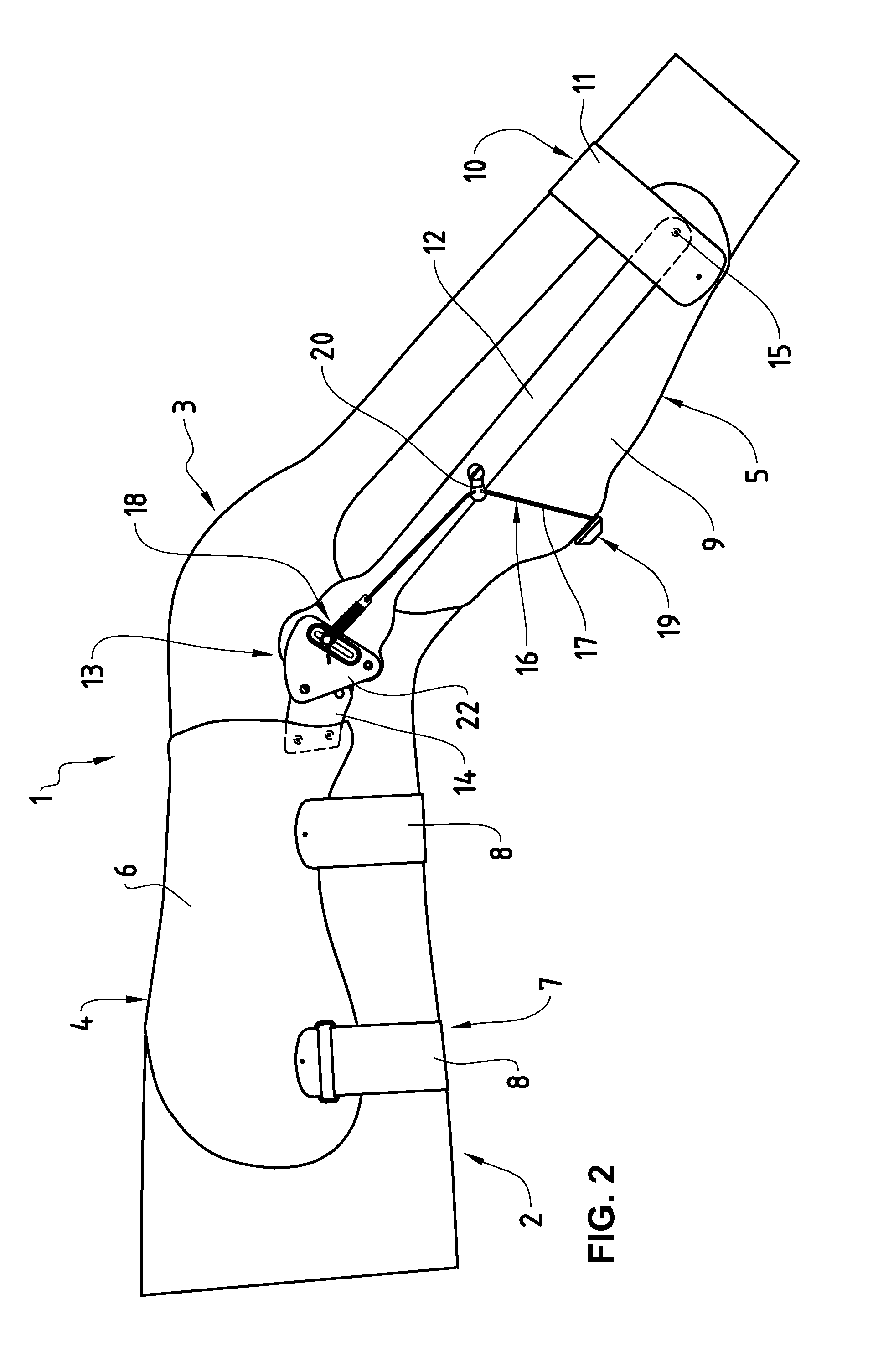
A knee orthosis (1) for support of a knee joint in the case of instability comprises a thigh portion (4), which is attachable on the thigh, and a lower leg portion (5), which is attachable on the lower leg, which lower leg portion (5) is provided with splint elements (12), which are connected in an articulated way, via articulation means (13), to hinge plates (14) attached on the thigh portion (4). The lower leg portion (5) has a lower half shell (9), which in the region remote from the knee is borne in the splint elements (12) in a way pivotable about a pivot axis (15). Via a longitudinally stable, flexible traction (17) the lower half shell (9) is pushed ventrally against the lower leg, the pressure increasing with bending of the knee. An optimal support of the knee joint is thereby achieved, especially when the cruciate ligaments are injured.

Description

CROSS-REFERENCE TO RELATED APPLICATIONS[0001]This application claims priority to and the benefit of European Application No. 14173966.4, filed Jun. 25, 2014, the entire disclosure of which as is hereby incorporated by reference herein.BACKGROUND[0002]1. Related Field[0003]The present invention relates to a knee orthosis for support of a knee joint in the case of instability, comprising a thigh portion, attachable on the thigh via fixing means, with an upper half shell and hinge plates fixed to the half shell, a lower leg portion, attachable to the lower leg via fixing means, with a lower half shell and splint elements attached laterally on the lower half shell, which splint elements are connected to the respective hinge plate via articulation means and in which splint elements, in the regions remote from the articulation means, the lower half shell is pivotably borne about a pivot axis and is pivotable toward the lower leg via adjustment means.[0004]2. Related Art[0005]Especially wi...

Claims


Application Information

Patent Timeline
Patent Type & Authority Applications(United States)
IPC IPC(8): A61F5/01
CPCA61F2005/0137A61F2005/0155A61F2005/0132A61F5/0123A61F2005/0179
Inventor BOSSHARD, ADRIANKOHL, SANDRO
Owner ORTHO TEAM
Learn More