Flow meter unit with water-tight casing

a flow meter and casing technology, applied in the direction of volume/mass flow measurement, measurement devices, instruments, etc., can solve the problems of high manufacturing cost, high complexity, high cost and large timeframe, etc., to achieve low complexity, long life-time, and high versatility

Active Publication Date: 2015-12-31
KAMSTRUP
View PDF1 Cites 12 Cited by
  • Summary
  • Abstract
  • Description
  • Claims
  • Application Information

AI Technical Summary

Benefits of technology

[0014]In view of the above, it may be seen as an object of the present invention to provide an improved ultrasound flow meter for ultrasonic measurement of a fluid flow and an improved method of manufacturing of a flow meter which has a lower level of complexity than methods of manufacturing applied in the prior art, and still the meter should provide a high versatility and provide a long life-time.
[0016]Such unit is advantageous, since the water-tight casing around the transducers and electronic circuit serve to protect these parts against humidity, and thus even if the unit is used for a cooling meter, the sensitive parts are protected against humidity which ensures a long life-time of these parts. Still, the common protection membrane is understood to allow penetration of ultrasound signals to and from the first and second ultrasound transducers, preferably the first and second ultrasound transducer are arranged such within the water-tight casing, that they transmit and receive ultrasound signals through the common protection membrane in a direction substantially parallel with each other, and wherein this direction is preferably perpendicular to a plane extended by the common protection membrane.
[0019]Further, such unit provides a high versatility, since it can be used in a large number of different applications, i.e. mounted on different types of housing and measuring tube arrangements, whether forming part of a consumption meter or forming part of another type of application where a measurement of fluid flow is required. The unit is highly suited for different applications and can thus be manufactured as a low cost component, since one single version can fit many applications, thus enabling large scale manufacturing using a highly automated production line. Still further, the manufacturing is facilitated by the rather low number of single element required thus also reducing the necessary number of single manufacturing steps, especially in versions where the transducers are soldered directly onto the surface of the circuit board using automated Surface Mounting Technology.
[0020]The invention provides a highly versatile stand-alone unit for a large variety of applications where a flow rate of a fluid is to be measured. A simple electrical interface can be provided, e.g. where the measured flow rate is output as pulses. This interface may be reduced down to one single electrical pin, see e.g. European patent application publication No. EP 2 042 837, e.g. with part of the casing being a metal serving as electrical ground connector. Hereby, the unit is easy to fit into different applications. In some embodiments, a battery is provided within the water-tight casing, thus allowing a completely self-contained flow meter unit with a simple electric interface.
[0026]The common protection membrane may have first and second recesses shaped so as to receive the first and second ultrasound transducers, respectively. This facilitates the mounting of the ultrasound transducers with respect to the common protection membrane.
[0027]Preferably, the first and second ultrasound transducers form a mechanically separate unit together with the circuit board, preferably using Surface Mounting Technology for mounting the two ultrasound transducers on the circuit board. This is essential for effective production, since the mechanically separate unit including transducers and circuit board forms already a functioning unit before this separate unit is mounted in the water-tight casing. Thus, before the final assembly steps of mounting this separate unit in the water-tight casing, it can be tested in a test setup and thus rejected at an early state prior to providing the final flow meter unit. Hereby, the production cost can be lowered since failing species are revealed at an early state, and in addition the rather complex handling of wires and connecting of wires between transducers and circuit board in automated manufacturing has been eliminated. Also, a more reliable flow meter can be achieved due to fewer parts and connections. Moreover, this can also lead to an increase in lifetime of the ultrasound flow meter. In addition, higher precision is possible as a result of reduced tolerances.

Problems solved by technology

The through-going holes are necessary since the ultrasonic signals are poor at penetrating directly through metallic materials.
However, one common problem with prior art ultrasound flow meters is that the level of complexity, and consequently high expenditures and large timeframes, involved with the manufacturing are too high.
A further problem is that the mentioned way of manufacturing an ultrasound flow meter necessitates that several parts are dedicated for used with one specific type of housing, and thus a large number of specially designed parts must be manufactured for each flow meter version.
Still further, it is a problem that it is difficult to protect electronic parts of a flow meter against humidity such that these parts can have a long life-time, e.g. of 20 years, even if the meter is installed in a humid environment.
Moreover, this can also lead to an increase in lifetime of the ultrasound flow meter.
In addition, higher precision is possible as a result of reduced tolerances.

Method used


Image

  • Flow meter unit with water-tight casing
  • Flow meter unit with water-tight casing
  • Flow meter unit with water-tight casing

Examples


Embodiment Construction

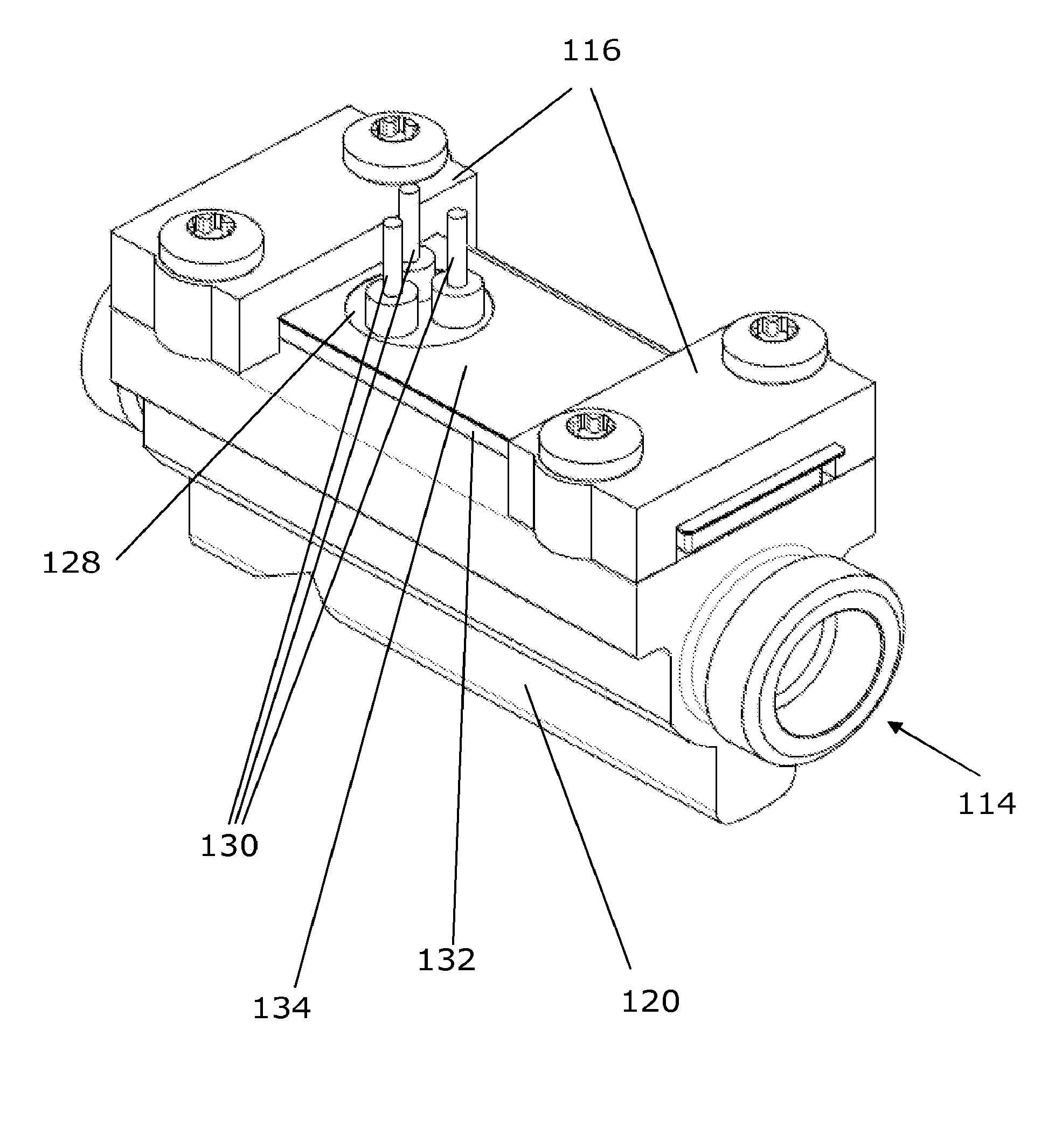
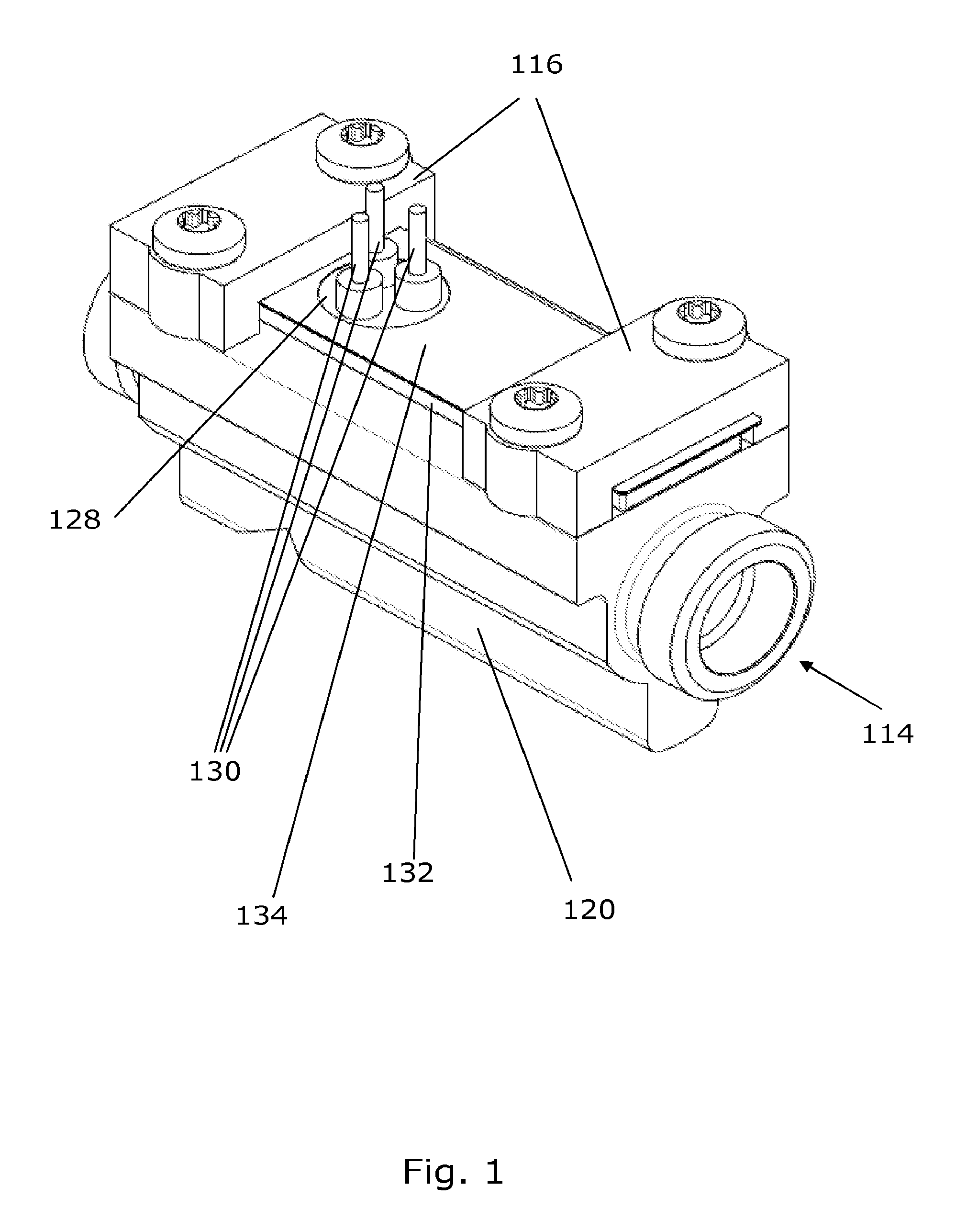
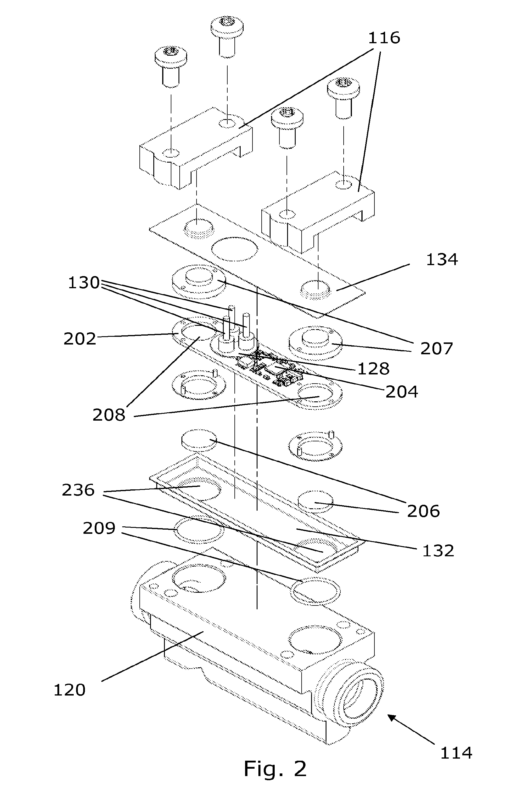
[0038]FIG. 1 shows a perspective view of an ultrasound flow meter with a metallic flow meter housing 120, with a measuring tube 114 adapted for fluid flow inside. Attached to the flow meter housing 120 is a water-tight casing enclosing two ultrasound transducers and a circuit board with an electronic circuit for controlling the ultrasound transducers. The water-tight casing comprises a top-part 134 and a common protection membrane 132. The common protection membrane 132 is metallic in the shown embodiments, but other embodiments where the common protection membrane 132 is made of other materials, such as polymeric materials, are possible. The two parts 132, 134 forming the water-tight casing may be assembled in different ways, e.g. using a welding process in case both parts 132, 134 are of metal, however the two parts 132, 134 are preferably shaped to match together and the assembly process is selected so as to form a robust water-tight sealing between the two parts, e.g. using the ...


PUM


Abstract

An ultrasound flow meter unit, e.g., a unit forming part of a flow meter for ultrasonic measurement of a fluid flow. The unit comprises two ultrasound transducers 206, a circuit board 202 with an electronic circuit 204 arranged for operating the ultrasound transducers 206, and a common protection membrane 132, such as a sheet of metal, for protecting the transducers 206. The common protection membrane 132 forms part of a water-tight casing, such as an IP68 class casing. The two ultrasound transducers 206 and the circuit board 202 with the electronic circuit 204 are positioned within the water-tight casing and thus protected against damaging humidity. A glass sealed feed-through 128 can be used to provide external electrical contact to the electronic circuit 204, i.e. for outputting an electric flow rate signal. Such flow meter unit is highly versatile within many applications since it provides a compact and robust unit. The unit can be used with or integrated in many types of devices, e.g. flow meters, such as used in consumption meters for charging purposes or in many other industrial or home applications

Description

INCORPORATION BY REFERENCE TO ANY PRIORITY APPLICATIONS[0001]Any and all applications for which a foreign or domestic priority claim is identified in the Application Data Sheet as filed with the present application are hereby incorporated by reference under 37 CFR 1.57. This application is a continuation of U.S. application Ser. No. 13 / 255,724, filed as PCT Application PCT / DK2010 / 050066 on Mar. 25, 2010 the entire contents of which are hereby incorporated by reference.BACKGROUND[0002]1. Field of the Invention[0003]The invention relates to an ultrasound flow meter unit, such as for ultrasonic measurements of fluid flow as used e.g. in consumption meter. In particular the invention provides an ultrasound flow meter unit with a water-tight casing.[0004]2. Description of the Related Art[0005]Normally, ultrasound flow meters suited for measuring a fluid flow in connection with charging of a consumed quantity (e. g. heat, cooling, water or gas) will have a housing, which can be metallic o...

Claims


Application Information

Patent Timeline
Patent Type & Authority Applications(United States)
IPC IPC(8): G01F1/66G01F15/14
CPCG01F1/66G01F1/662G01F1/667G01F15/14
Inventor NIELSEN, SØREN TØNNES
Owner KAMSTRUP
Why Eureka
Try Eureka