Discharge ionization current detector

a technology detector, which is applied in the field of discharge ionization current detector, can solve the problems of limited analysis of compounds, and achieve the effect of preventing the deterioration of the s/n ratio of a detection signal at a high temperature and favorable measurement results

Active Publication Date: 2015-12-31
SHIMADZU CORP
View PDF2 Cites 2 Cited by
  • Summary
  • Abstract
  • Description
  • Claims
  • Application Information

AI Technical Summary

Benefits of technology

[0041]According to the discharge ionization current detector of the present invention, the deterioration of the S/N ratio of a detection signal a...

Problems solved by technology

The FID has the characteristic of a wide dynamic range, but compounds to be analyzed ar...

Method used


Image

  • Discharge ionization current detector
  • Discharge ionization current detector
  • Discharge ionization current detector

Examples


first embodiment

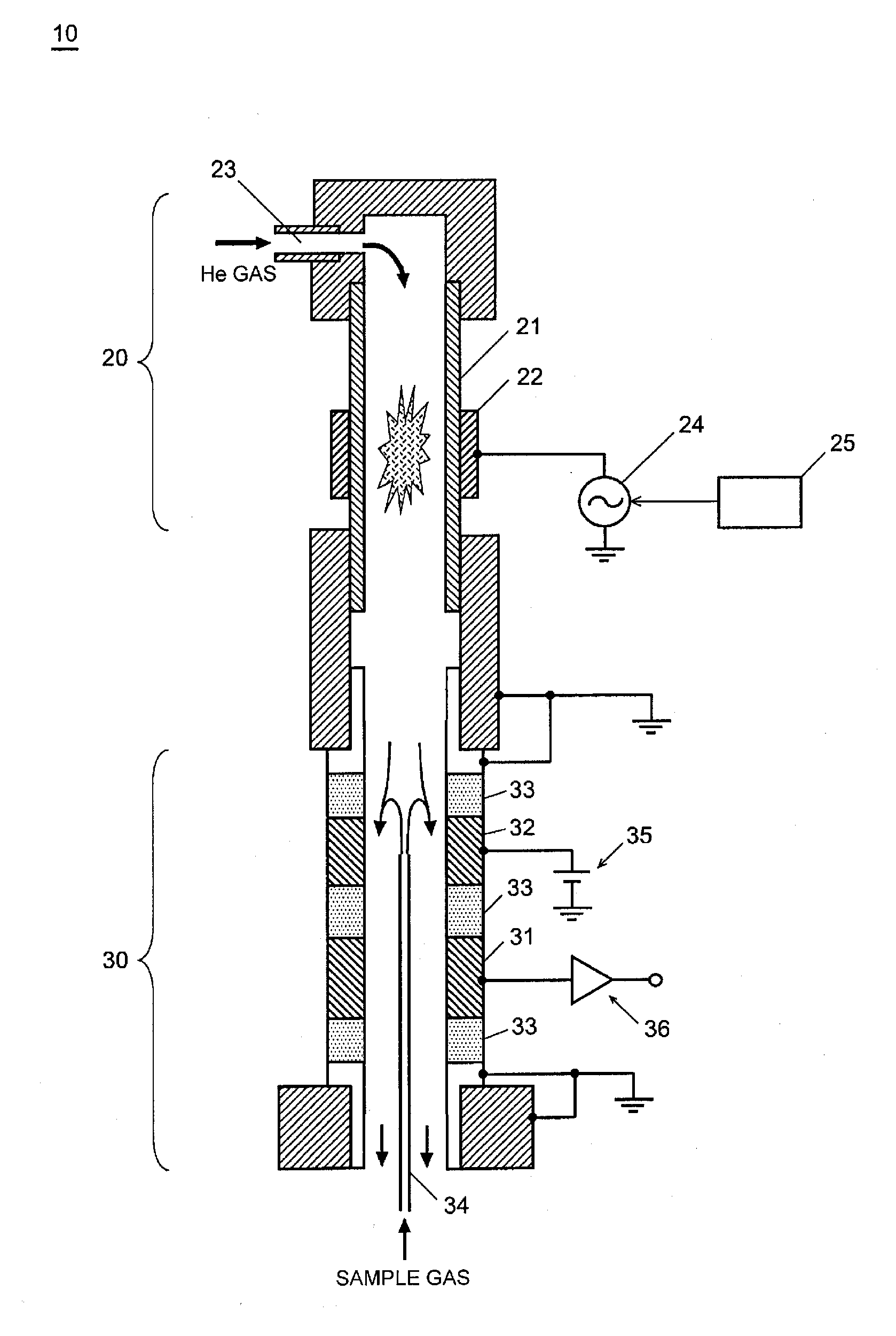
[0053]FIG. 1 is a schematic configuration view of a discharge ionization current detector of the present invention and illustrates the cross section of a discharge ionization current detector 10 formed in a cylindrical shape. The discharge ionization current detector 10 is mainly constituted of a plasma generating section 20 and an ion collecting section 30.

[0054]A gas introduction port 23 is provided above the plasma generating section 20, and a cylindrical pipe 21 made of a dielectric substance such as synthetic quartz is provided below the gas introduction port 23. A plasma generating electrode 22 is arranged on the outer side of the cylindrical pipe 21, and a low-frequency alternating-current power supply 24 is connected to the electrode 22. The alternating-current power supply 24 is provided in such a manner as to be capable of controlling voltages and frequencies by means of a controller 25.

[0055]Regarding the ion collecting section 30, an insulating member 33, a bias electrod...

second embodiment

[0070]Hence, in the discharge ionization current detector of the present invention, the ion collecting section may be constituted, for example, as illustrated in FIG. 3. With this constitution, metallic O-rings 55 are arranged on the contact surfaces of an ion collecting electrode 51, insulating members 53, and a bias electrode 52, and airtightness is secured by pushing the O-rings 55 with a plate spring 56. Inconel (registered trademark), for example, may be preferably used as a material of the metallic O-rings 55. The Inconel is a nickel base superalloy that excels in shape restoring ability at high temperatures, and use of the Inconel can prevent the plastic deformation of the O-rings due to the temperature cycles. Also, gold plating or silver plating may be applied to the surfaces of the O-rings, in order to prevent the oxidation of the O-rings 55.

[0071]Alternatively, as another embodiment, the ion collecting section may be constituted as illustrated in FIG. 4 (third embodiment)...


PUM


Abstract

A discharge ionization current detector of the present invention is used for a detector for a gas chromatograph and suitable for analyzing high-boiling components. A discharge ionization current detector 10 is mainly constituted by a plasma generating section 20 and an ion collecting section 30. Regarding the ion collecting section 30, an ion collecting electrode 31 and a bias electrode 32 are arranged, and furthermore, an insulating member made of sapphire or aluminum oxide having a purity equal to or greater than 99.5% is arranged between the ion collecting electrode 31 and the bias electrode 32.

Description

TECHNICAL FIELD[0001]The present invention relates to a discharge ionization current detector primarily suitable as a detector for a gas chromatograph (GC), and more particularly relates to improvement in the characteristics of the detector at a high temperature.BACKGROUND ART[0002]As a detector for GC, the detectors of various types, such as a flame ionization detector (FID), a pulsed discharge detector (PDD), and a thermal conductivity detector (TCD), have been conventionally in practical use.[0003]Among the aforementioned detectors, the FID is generally used in order to detect organic substances. The FID ionizes sample components in sample gas with hydrogen flames and detects a resultant ion current. The FID has the characteristic of a wide dynamic range, but compounds to be analyzed are limited because the sample is burned in the hydrogen flames to ionize the sample components. The FID has low sensitivity with respect to incombustible gas and no sensitivity with respect to inorg...

Claims


Application Information

Patent Timeline
IPC IPC(8): G01N30/64
CPCG01N27/70G01N2030/025G01N2030/647G01N30/64
Inventor HORIIKE, SHIGEYOSHISHINADA, KEI
Owner SHIMADZU CORP
Why Eureka
Try Eureka