[0025]Thus, a capacitive sensor device is provided without needing complex fabrication methods for fabricating further additional conducting
layers that would lead to additional
processing steps and the need of
processing masks for instance. Without the need of further conducting
layers over further
interconnection layers, further
processing steps may be needless and hence planarization problems and fabrication costs may be reduced.
[0029]The impedance is Z=1 / jωC1++1 / jωC2 with j the imaginary number and ω the frequency ω=2*πf. Z is an imaginary number and frequency dependent. The impedance may be plotted in a parabola graph and is actually the modulus of the impedance. I.e. an
equivalent capacitance of the series circuit of the first
capacitor and the second capacitor is equal to 1 / Ceq=1 / C1+1 / C2. Thus, by connecting the first capacitor and the second capacitor in series, a capacitive readout circuitry may be provided, wherein capacitive readout circuitry results into a non-linear response. I.e., when in a diagram the axis of abscissas describes the displacement of the movable element and the impedance Z may be expressed in the axis of ordinates, a parabolic measurement curve may be measured. I.e., that for small movements of the movable element, the impedance Z is only changed little around the vertex of the curve, wherein for large movements of the movable element large changes in the impedance Z may be measured. Thus, in particular for high-g acceleration, a good measuring result may be achieved. On the other side, small acceleration that generates only a small movement of the movable element causes a small change in the impedance Z, so that the capacitive sensor of the present exemplary embodiment may filter small accelerations without further devices. Thus, without any additional filtering methods, small accelerations may be damped or filtered out. Furthermore, mismeasurements due to e.g. fabrication mismatches may be filtered out automatically because most of the fabrication mismatches would lead to a small movement of the movable element, so that this small movement of the movable element only leads to a small change in the measured impedance Z, so that no further measures have to be provided to correct the measuring. Hence, an incomplex sensor device may be provided.
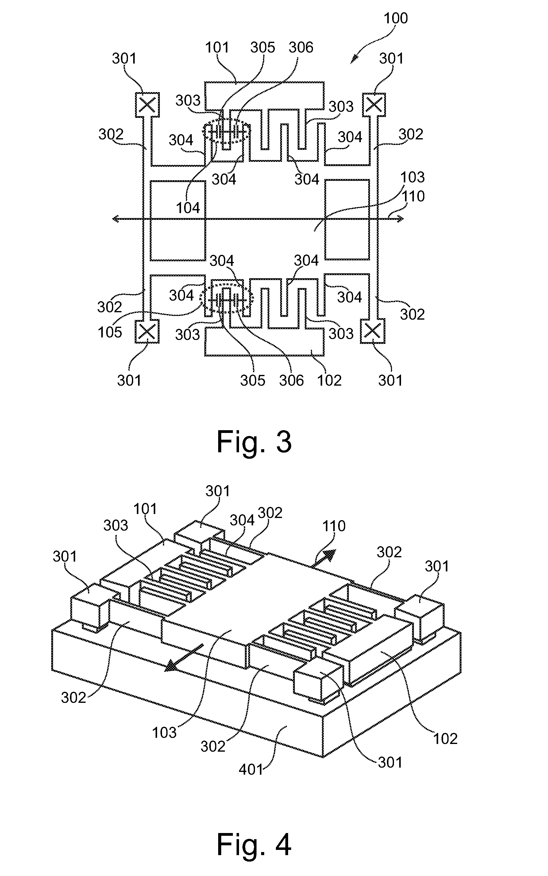
[0031]According to a further exemplary embodiment, the moveable element and at least one of the first electrode and the second electrode interdigitates with each other. According to a further exemplary embodiment, at least one of the first electrode and the second electrode comprise at least one electrode finger protruding in the direction to the movable element. The movable element comprises at least one movable finger protruding at least in the direction to the at least one of the first electrode and the second electrode. The electrode finger and the movable finger are adapted for interdigitating with each other. In other words, the movable element and the first electrode or second electrode engaging comb-shaped with the movable fingers and the electrode fingers. The capacitive sensor device, in particular the movable element and / or the represented first capacitor and / or the represented second capacitor, may comprise interdigitated finger electrodes which may be physically located at the electrode finger and / or the movable finger. The capacitively
coupling may be provided between the electrode finger and the movable finger. Thus, when providing interdigitating electrode fingers and movable fingers, the surface between the movable element and the first electrode or the second electrode may be increased, so that for instance larger capacitor electrodes and larger surfaces of the capacitor electrodes or capacitor plates may be provided for the capacitively
coupling. Thus, better measurement results may be achieved.
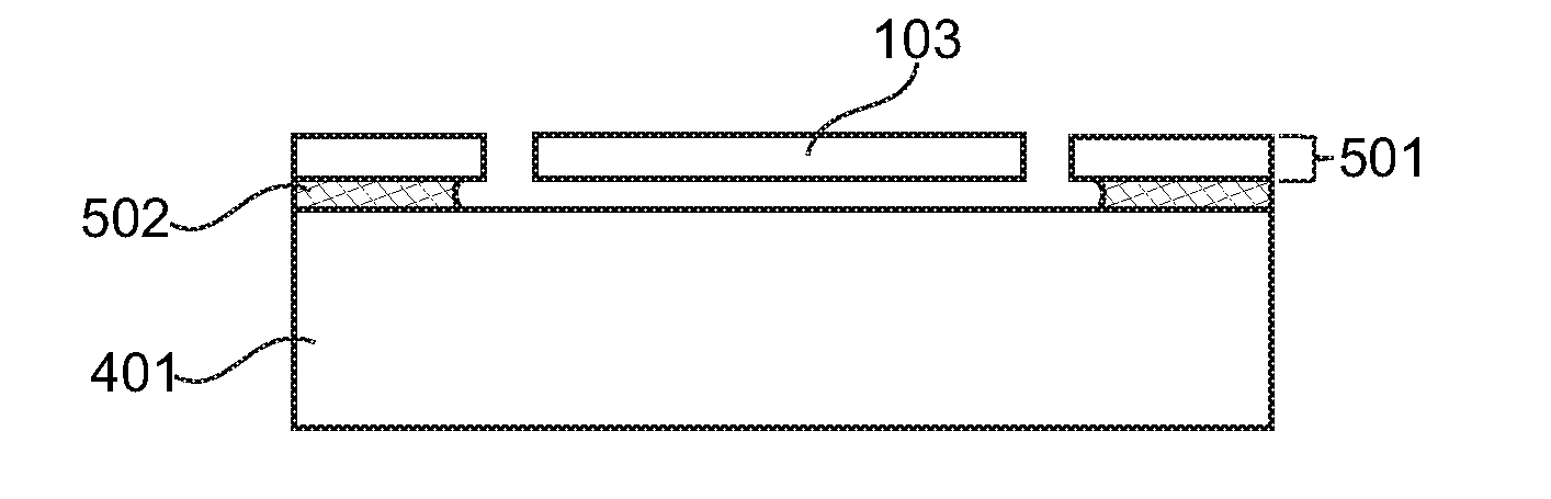
[0032]According to a further exemplary embodiment a method of producing a capacitive sensor device as denoted above is provided. According to the method, a substrate is provided. A
buried oxide layer is formed on the substrate and a top
silicon layer is formed on the
buried oxide layer. In the top
silicon layer
etching holes and trenches are etched, wherein a pattern of the holes and trenches are defined by a
mask. The
buried oxide layer located below the top
silicon layer is removed according to the pattern. For
crash and fall-detection sensors, a sensor is needed up to at least 1 g while
linearity is less an issue. The invention may provide a capacitive MEMS
accelerometer, which may be optimised for high-g applications. A
system layout is proposed in which the number of processing or fabricating steps of the device may be reduced and therefore the fabricating costs may decrease significantly.
[0033]Furthermore, the capacitive sensor device comprises a simple planar
accelerometer layout wherein only a few layers, in particular one, for both, the movable element and the first electrode and second electrode, may be needed. This may reduce the number of masks for the fabrication process of the device, e.g. to two masks, while in conventional devices five and more masks for the additional layers are needed.

